Patient Lift Device

a technology for lifting devices and patients, applied in hospital equipment, medical science, nursing beds, etc., can solve the problems of motors and their associated control circuitry failing periodically, significant problems associated with motorized lifting and lowering, and significant cost associated with including motors and associated control circuitry, so as to avoid or avoid failures

Inactive Publication Date: 2012-01-26
PRISM MEDICAL
View PDF11 Cites 9 Cited by
  • Summary
  • Abstract
  • Description
  • Claims
  • Application Information

AI Technical Summary

Benefits of technology

[0007]Therefore, what is preferred is a patient lift device that provides at least one of the advantages of motorized lifting and lowering, while also avoiding or mitigating at least one of the disadvantages of motorized lifting and lowering.

Problems solved by technology

There are significant problems associated with motorized lifting and lowering.
First, there is a substantial cost associated with including a motor, and associated control circuitry, in a lift.
Second, motors and their associated control circuitry can and do fail periodically.
The result is downtime for the lift, adversely affecting the disabled patient.
Third, when motorized lifts are used, they must be powered.
There are some challenges that this situation presents.
If the user forgets to recharge the batteries, the lift may run out of power when it is needed.
Alternatively, the lift may require such long and frequent use that there is insufficient time to recharge the batteries.
In addition, it is necessary to locate a convenient place and power source for recharging the batteries, which may be difficult.

Method used


Image

  • Patient Lift Device
  • Patient Lift Device
  • Patient Lift Device

Examples


Embodiment Construction

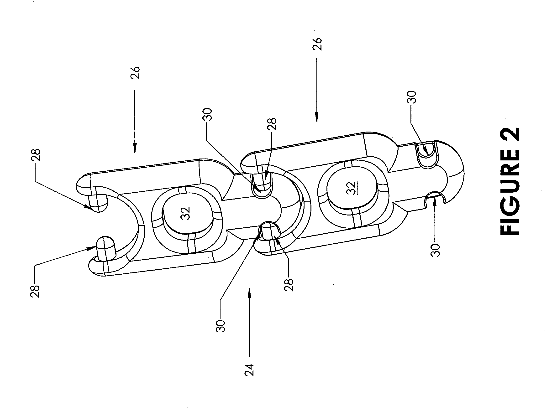
[0026]Referring now to FIG. 1, a patient lift device 10 according to the present invention is shown. Lift 10 includes a patient carrier for carrying a patient to be lifted. In the preferred embodiment shown in FIG. 1, the patient carrier comprises a pair of extended closeable hook members 12. Each of the hook members 12 is configured to receive a patient harness (not shown). To be lifted and lowered, a patient is placed in the harness that is held by hook members 12. Hook members 12 each include a displaceable arm 14 which can be opened to admit a strap or other portion of a patient harness. Once the harness is admitted into the hook member 12, the arm 14 is closed to hold the harness in place. The preferred arm 14 is biased to a closed position, and can be opened by manual application of force.

[0027]The lift 10 further includes a housing 16 which houses a lifting mechanism (described below). Extending outward from the top of the housing 16 is a handle 18 for carrying lift 10 when i...


PUM


Abstract

A patient lift device comprising: a patient carrier for carrying to a patient to be lifted; a support element sized, shaped and positioned to couple the patient lift device to an upper support; an unmotorized lifting mechanism, operatively connected to the patient carrier and support element so as to raise or lower the patient carrier when the unmotorized lifting mechanism is actuated; and a power tool coupling, operatively connected to the unmotorized lifting mechanism such that when a power tool is coupled to the power tool coupling and actuated, the unmotorized lifting mechanism is actuated, the power tool coupling being configured to detachably mate with a driven power tool head.

Description

FIELD OF THE INVENTION[0001]This invention relates to the field of care for and treatment of disabled patients, primarily those unable to stand or walk on their own. More particularly, this invention relates to lift devices for use in the care for and treatment of disabled patients.BACKGROUND OF THE INVENTION[0002]There are a wide variety of known patient lift devices. There are two broad categories of patient lifts: fixed and portable. A fixed lift is more or less permanently mounted on a track that is, typically, fixed to a ceiling. A strap for lifting and lowering a patient extends from the lift and carries a patient harness. The lift can extend or retract the strap to lower or lift the patient. The lift is also movable along the track. Typically, both the lift / lower function and the movement along the track are motorized, that is, powered by an electric (or other) motor.[0003]Portable lifts may be used either with fixed track, or with portable support frames that provide overhea...

Claims


Application Information

Patent Timeline
IPC IPC(8): A61G7/10
CPCA61G7/1015A61G7/1065A61G7/1061
Inventor CHEPURNY, MARK P.HASHEMI, VAHIDEH
Owner PRISM MEDICAL
Why Eureka
Try Eureka