
Voice coil motor

a voice coil motor and motor body technology, applied in the direction of instruments, printers, cameras, etc., can solve the problems of increasing manufacturing costs, difficult to accurately adjust the interval between the lens and the image sensor, and complicated manufacturing processes

Active Publication Date: 2012-01-12
LG INNOTEK CO LTD
View PDF2 Cites 88 Cited by
  • Summary
  • Abstract
  • Description
  • Claims
  • Application Information

AI Technical Summary

Benefits of technology

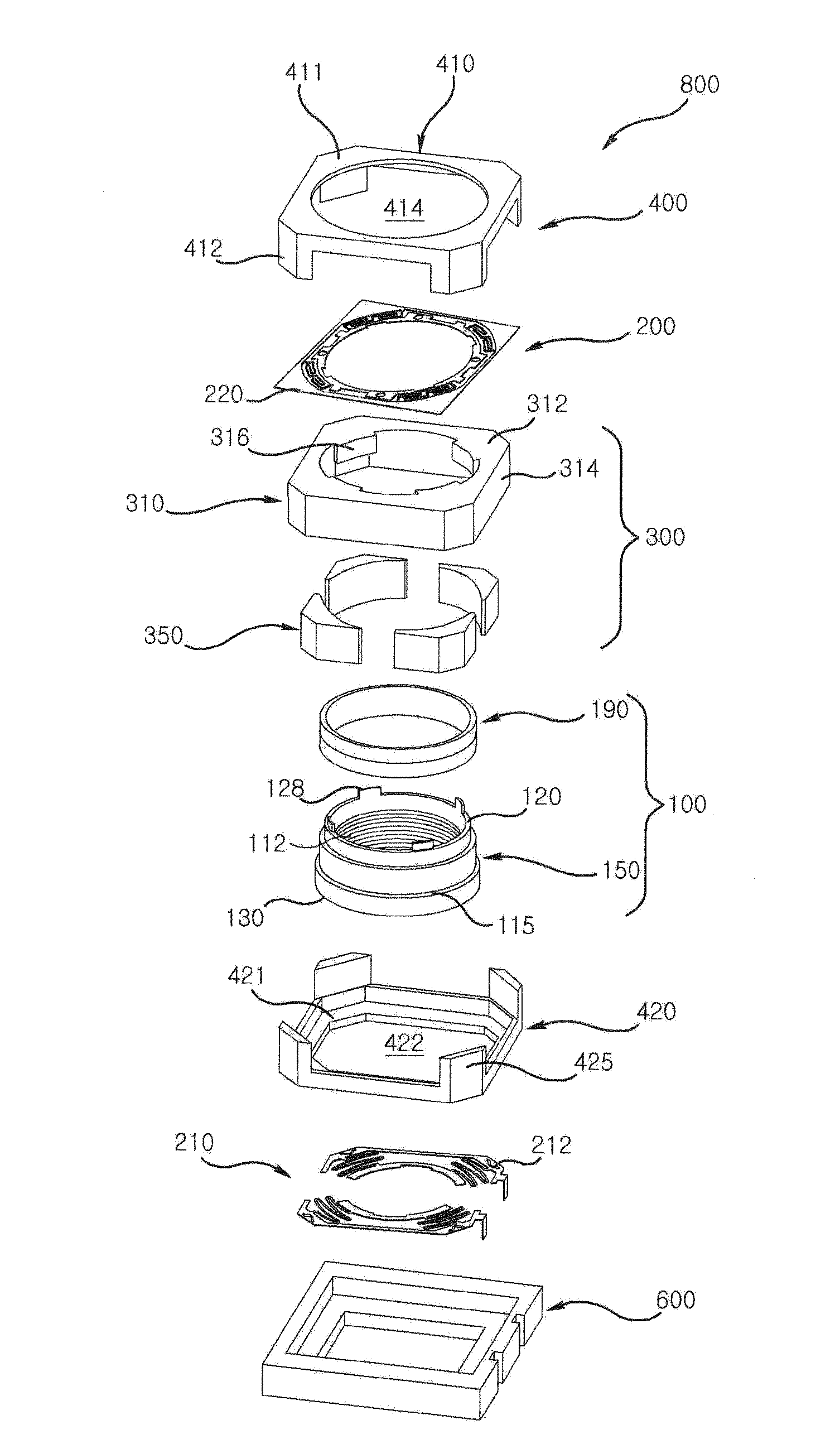
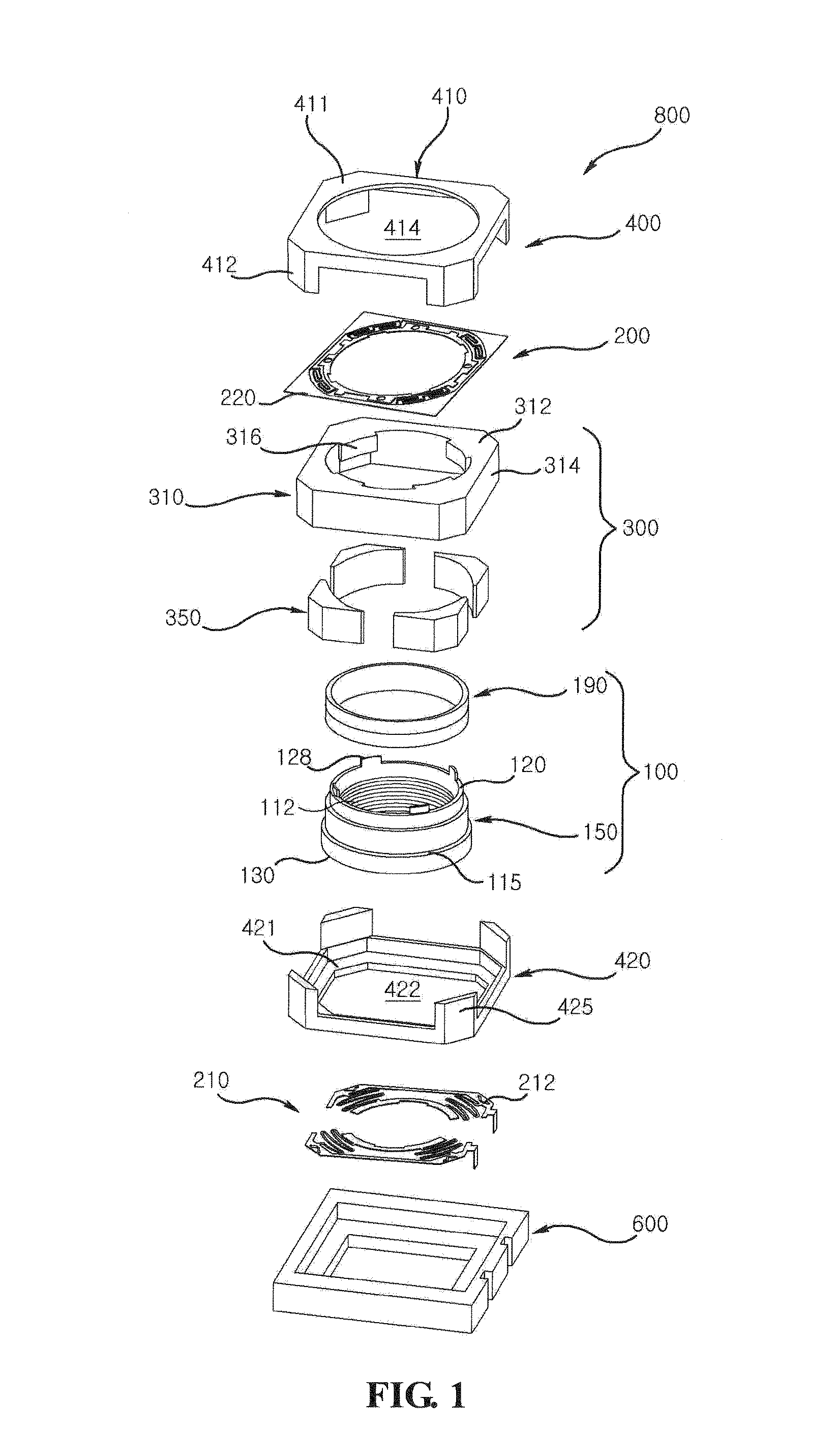
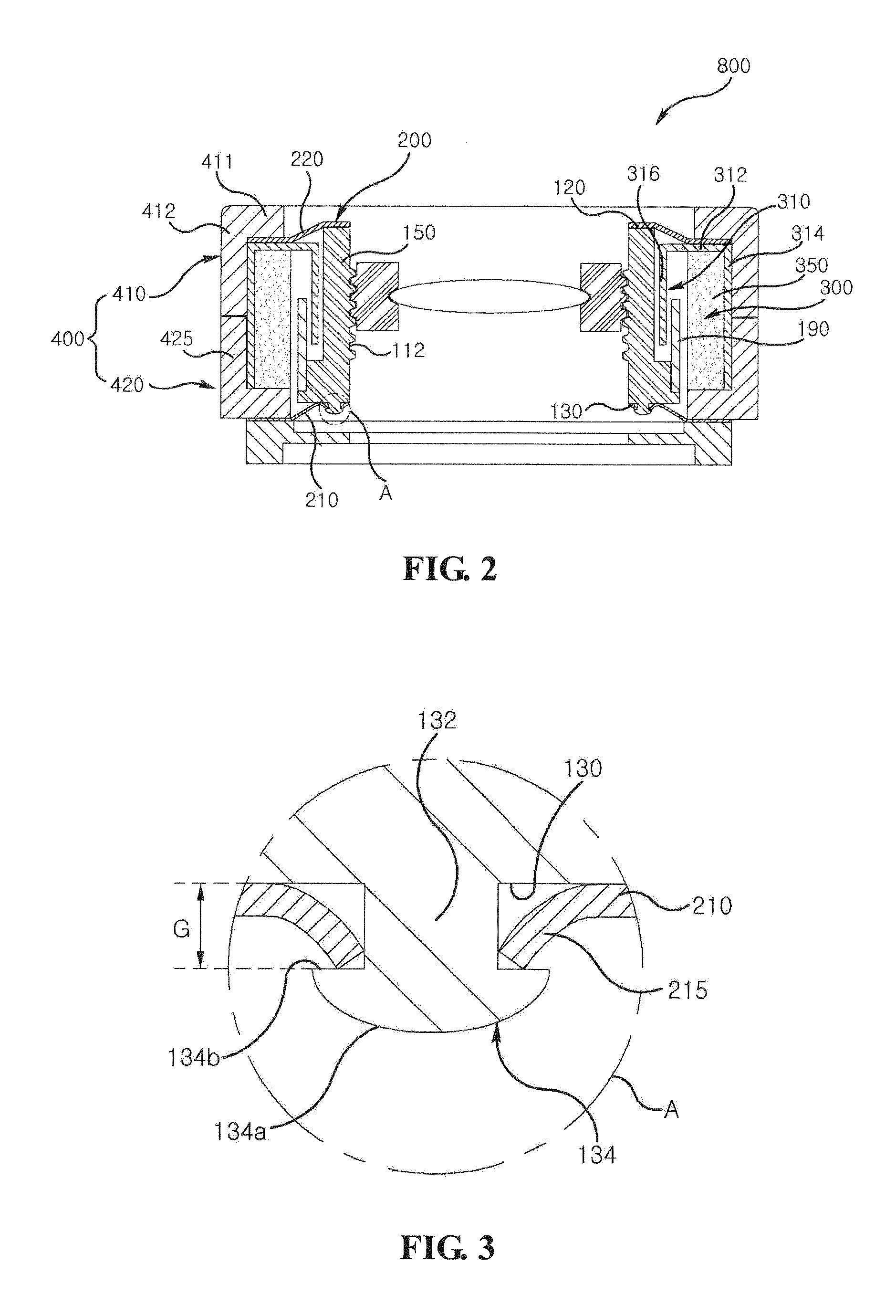
[0019]The present disclosure is directed to cope with the abovementioned problems and to provide a VCM (voice coil motor) configured to remove a gap generated between a bobbin and an elastic member to accurately adjust an interval between a lens and an image sensor.
[0020]The present disclosure is to provide a VCM configured to increase reliability by reducing a manufacturing cost and preventing an elastic member arranged on a distal end of a bobbin from being disengaged from the distal end of the bobbin by a shock or a vibration applied from outside.
[0021]The present disclosure is to provide a VCM configured to enhance a coupling power of an elastic member between a coil forming a coil block arranged on a periphery of a bobbin and an elastic member electrically connected to the coil.
[0025]The VCM according to the present disclosure has an advantageous effect in that the elastic member is prevented from moving from the bobbin by a gap formed by the bobbin and the elastic member elastically supporting the bobbin to accurately control a distance between the lens mounted on the bobbin and the image sensor.
[0031]The VCM according to the present disclosure has an advantageous effect in that the adhesive guide lugs are formed at the bobbin coupled to the elastic member to prevent the elastic member from being deformed and damaged.

Problems solved by technology

However, the conventional VCM suffers from disadvantages in that a gap is frequently generated between the bobbin and the elastic member arranged under the bobbin by a manufacturing tolerance of the bobbin and the elastic member, and it is difficult to accurately adjust an interval between a lens and an image sensor due to the gap between the bobbin and the elastic member arranged under the bobbin.
In a case the part of the leaf spring is coupled to the bobbin by way of insert method according to the prior art, a manufacturing process becomes complicated to increase a manufacturing cost, and in a case the leaf spring is inserted into the bobbin to deform the leaf spring, the leaf spring and the bobbin are disadvantageously disposed of altogether.
Another disadvantage is that in a case the leaf spring is coupled to the bobbin by the thermal fusion method, the leaf spring is disengaged from the bobbin due to vibration and / or shock applied from outside, because an attachment strength between the bobbin and the leaf spring is smaller than that of the insert method.
However, another disadvantage is generated that it is difficult to improve a coupling strength between the bobbin and the leaf spring due to smaller adhesive coated area between the leaf spring and the bobbin.
Still another disadvantage is that the coil electrically connected to the leaf spring is short-circuited due to the leaf spring being disengaged from the bobbin.
Still further disadvantage is that the bobbin and the leaf spring are mutually bonded by an adhesive, and in a case the bobbin and the leaf spring are bonded by the adhesive provided by a dispenser, the leaf spring is separated along with the dispenser when the leaf spring is separated after the adhesive is coated to the leaf spring using the dispenser, to damage the leaf spring and / or cause an adhesive imperfection to the bobbin and the leaf spring.

Method used


Image

  • Voice coil motor
  • Voice coil motor
  • Voice coil motor

Examples


Embodiment Construction

[0058]Advantages and features of the present invention may be understood more readily by reference to the following detailed description of exemplary embodiments and the accompanying drawings. Detailed descriptions of well-known functions, configurations or constructions are omitted for brevity and clarity so as not to obscure the description of the present disclosure with unnecessary detail. Thus, the present disclosure is not limited to the exemplary embodiments which will be described below, but may be implemented in other forms. In the drawings, the width, length, thickness, etc. of components may be exaggerated or reduced for the sake of convenience. Furthermore, throughout the descriptions, the same reference numerals will be assigned to the same elements in the explanations of the figures, and explanations that duplicate one another will be omitted. Accordingly, the meaning of specific terms or words used in the specification and claims should not be limited to the literal or...


PUM


Abstract

A VCM (voice coil motor) is disclosed, the VCM including: a rotor including a cylindrical bobbin for accommodating a lens and protruded at a bottom end with a boss, and a coil block arranged at a periphery of the bobbin; a stator including a magnet facing the coil block and a yoke fixing the magnet; and an elastic member including a first elastic member formed with a through hole coupled to the boss of the bobbin and a second elastic member coupled to an upper end facing the bottom end of the bobbin; wherein the boss is formed with a disengagement prevention unit preventing the first elastic member from being disengaged from the boss, and the first elastic member is formed with a coupling unit contacting a joint where the disengagement prevention unit and the coupling unit meet.

Description

CROSS-REFERENCE TO RELATED APPLICATIONS[0001]This application claims the benefit under 35 U.S.C. §119 of Korean Patent Application Nos. 10-2010-0067051, filed Jul. 12, 2010; 10-2010-0071326, filed Jul. 23, 2010; 10-2010-0071635, filed Jul. 23, 2010; and 10-2010-0102737, filed Oct. 21, 2010, which are hereby incorporated by reference in their entirety.BACKGROUND OF THE DISCLOSURE[0002]1. Field of the Disclosure[0003]The present disclosure relates to a voice coil motor.[0004]2. Description of the Related Art[0005]Recently, a small optical device such as a super-small digital camera on a mobile phone or a high resolution digital camera has been developed and is formed with an actuator for adjusting magnification and focus. The camera on the mobile phone or the digital camera recently employs an actuator such as a VCM (voice coil motor) on a wide range base.[0006]The conventional super-small digital camera on the mobile phone is such that it is impossible to adjust a gap between an imag...

Claims


Application Information

Patent Timeline
Patent Type & Authority Applications(United States)
IPC IPC(8): G02B7/04
CPCG02B7/04H02K41/0356H02K41/0354G02B7/02G03B3/10G03B13/34H02K41/031G11B7/00H02K41/03
Inventor MIN, SANGJUNLEE, SANGHEEYOO, HYUNEOKIM, SEUNGKIHAN, JINSUK
Owner LG INNOTEK CO LTD
Learn More