Vehicle antenna
a technology for vehicle antennas and antennas, applied in the field of vehicle antennas, can solve the problems of deterioration of isolation characteristics, gps signals, tdmb signals, etc., and achieve the effect of improving space utilization and improving antenna characteristics
- Summary
- Abstract
- Description
- Claims
- Application Information
AI Technical Summary
Benefits of technology
Problems solved by technology
Method used
Image
Examples
first embodiment
[0054]FIG. 5 is a perspective view illustrating feeding structure of an antenna for a vehicle according to the present invention.
[0055]In FIG. 5(A) to FIG. 5(C), a first coupling side 500 is formed on the outer surface of the case 300, and a second coupling side 502 is formed on a location facing to the first coupling side 500 of the inner surface of the case 300. Here, each of the coupling sides 500 and 502 is a conductor.
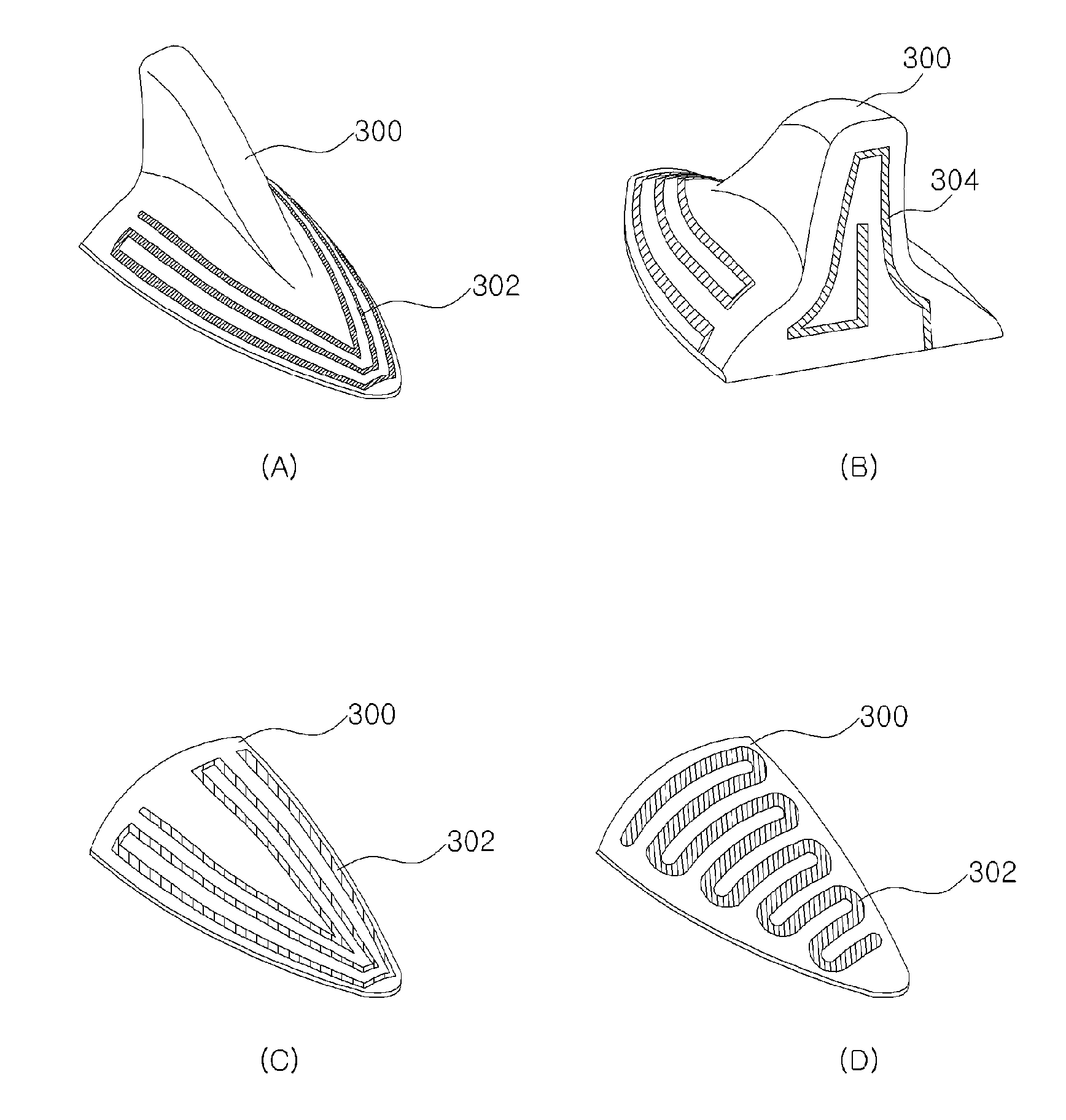
[0056]The first coupling side 500 is electrically connected to for example the first radiator 302 as shown in FIG. 5(B). Here, the case 300 has streamlined shape in FIG. 3, but FIG. 5(B) shows only part of the case 300 to have plane shape for convenience of description.
[0057]The second coupling side 502 is connected to a feeding member 504. Here, the feeding member 504 is a conductor, and is electrically connected to a substrate 506, e.g. PCB as shown in FIG. 5(C). Accordingly, a power fed from the substrate 500 is delivered to the second coupling side 502 through...
second embodiment
[0060]FIG. 6 is a sectional view illustrating feeding structure of an antenna for a vehicle according to the present invention.
[0061]In FIG. 6, the antenna of the present embodiment may include further a connection member 600 extended to the inner surface from the outer surface of the case 300.
[0062]The connection member 600 is a conductor, an end of the connection member 600 is electrically connected to a part of the first radiator 302, and the other end of the connection member 600 is electrically connected to a feeding member 602.
[0063]Since the feeding member 602 is electrically connected to the substrate 506, a power fed from the substrate 506 is provided to the first radiator 302 formed on the outer surface of the case 300 through the feeding member 602 and the connection member 600.
[0064]The above direct feeding method may provide much power to the first radiator 302 compared to the coupling method in the first embodiment. However, since the connection member 600 is extended ...
third embodiment
[0065]FIG. 7 is a sectional view illustrating feeding structure of an antenna for a vehicle according to the present invention.
[0066]In FIG. 7, in the antenna of the present invention, a hole is formed through the case 300, and a feeding member 700 passes through the hole.
[0067]The feeding member 700 is directly connected to the first radiator 302 with extended from the substrate 506.
PUM
 Abstract
Description
Claims
Application Information
 - R&D
- Intellectual Property
- Life Sciences
- Materials
- Tech Scout
- Unparalleled Data Quality
- Higher Quality Content
- 60% Fewer Hallucinations
Browse by: Latest US Patents, China's latest patents, Technical Efficacy Thesaurus, Application Domain, Technology Topic, Popular Technical Reports.
© 2025 PatSnap. All rights reserved.Legal|Privacy policy|Modern Slavery Act Transparency Statement|Sitemap|About US| Contact US: help@patsnap.com


