Roller support for the point rail of a railroad switch

a rail switch and roller support technology, applied in railway tracks, railway ways, constructions, etc., can solve the problems of work-related additional expenses and time delays on the construction site, significant wear on the slide chair or the slide surface of the rail base plate, and the inability to fully install the roller assembly

Active Publication Date: 2012-01-05
SCHWIHAG
View PDF3 Cites 8 Cited by
  • Summary
  • Abstract
  • Description
  • Claims
  • Application Information

AI Technical Summary

Benefits of technology

[0012]It is therefore an object of the present invention to provide an improved roller support for the point rail of a railroad switch.
[0018]In a preferred configuration of the invention the roller support is a two-arm lever having a horizontally extending arm that holds the roller and a vertically downwardly extending arm that is biased by the spring subassembly. The two-arm lever and the spring subassembly acting on the vertical arm extend transverse to the stock rail and are under the point rail. Thus, they are located directly laterally beside the rail base plate between two switch sleepers or rail fastening points. On the one hand, this arrangement offers good protection against damage and, on the other, at the same time, a sufficiently large free space between the switch sleepers so that consolidating the ballast in this region by tamping can be done even after installation of the roller assembly.

Problems solved by technology

When running over the point rail, this state can result in significant wear on the slide chairs or the slide surfaces of the rail base plates because the point rail is brought in an undesirable manner into abutment against the support cleats only by the transverse force of the wheel running over the point rail.
Further, this roller assembly can only be assembled after the switch system has been installed on site.
This results in work-related additional expenses and time delays on the construction site.

Method used


Image

  • Roller support for the point rail of a railroad switch
  • Roller support for the point rail of a railroad switch
  • Roller support for the point rail of a railroad switch

Examples


Embodiment Construction

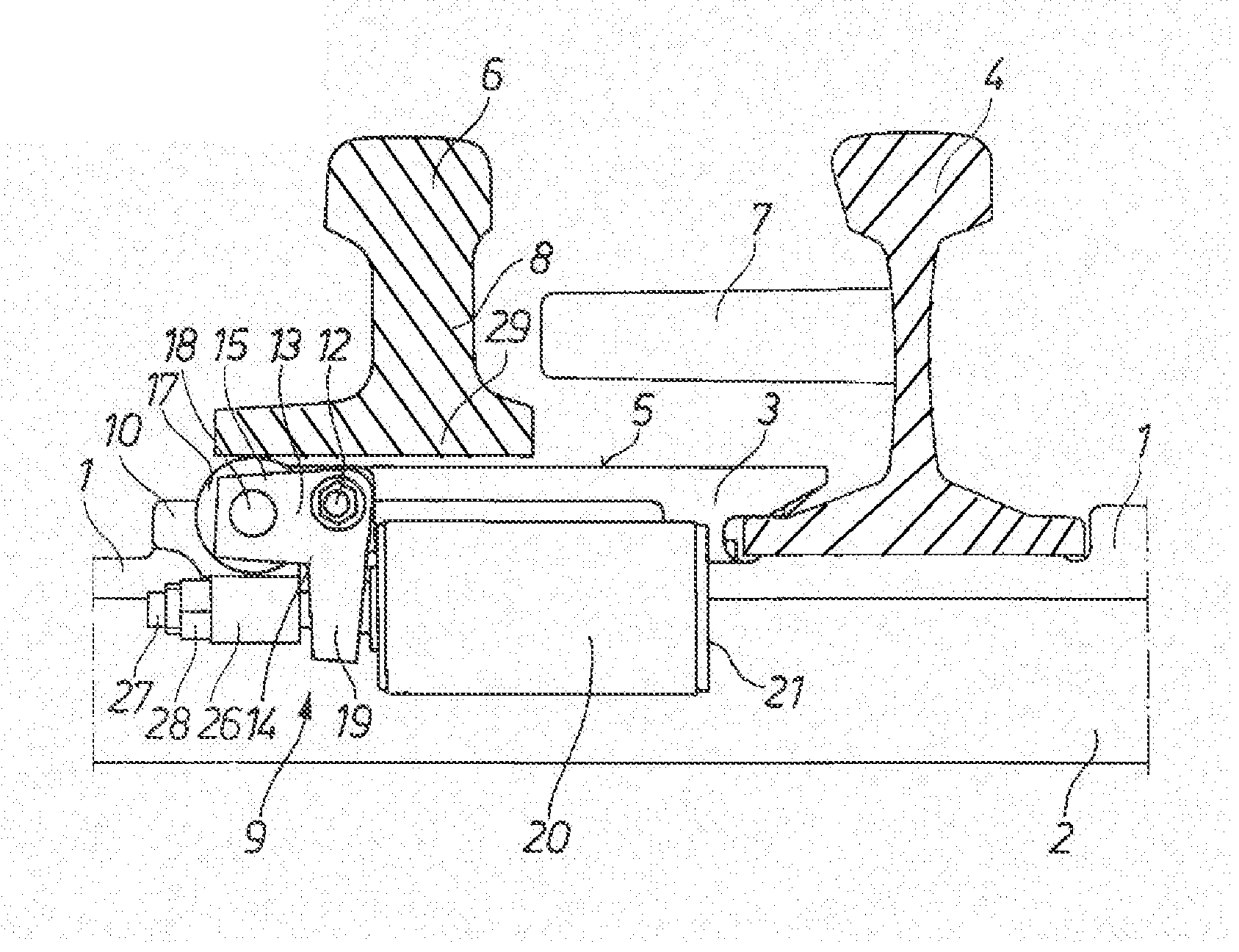
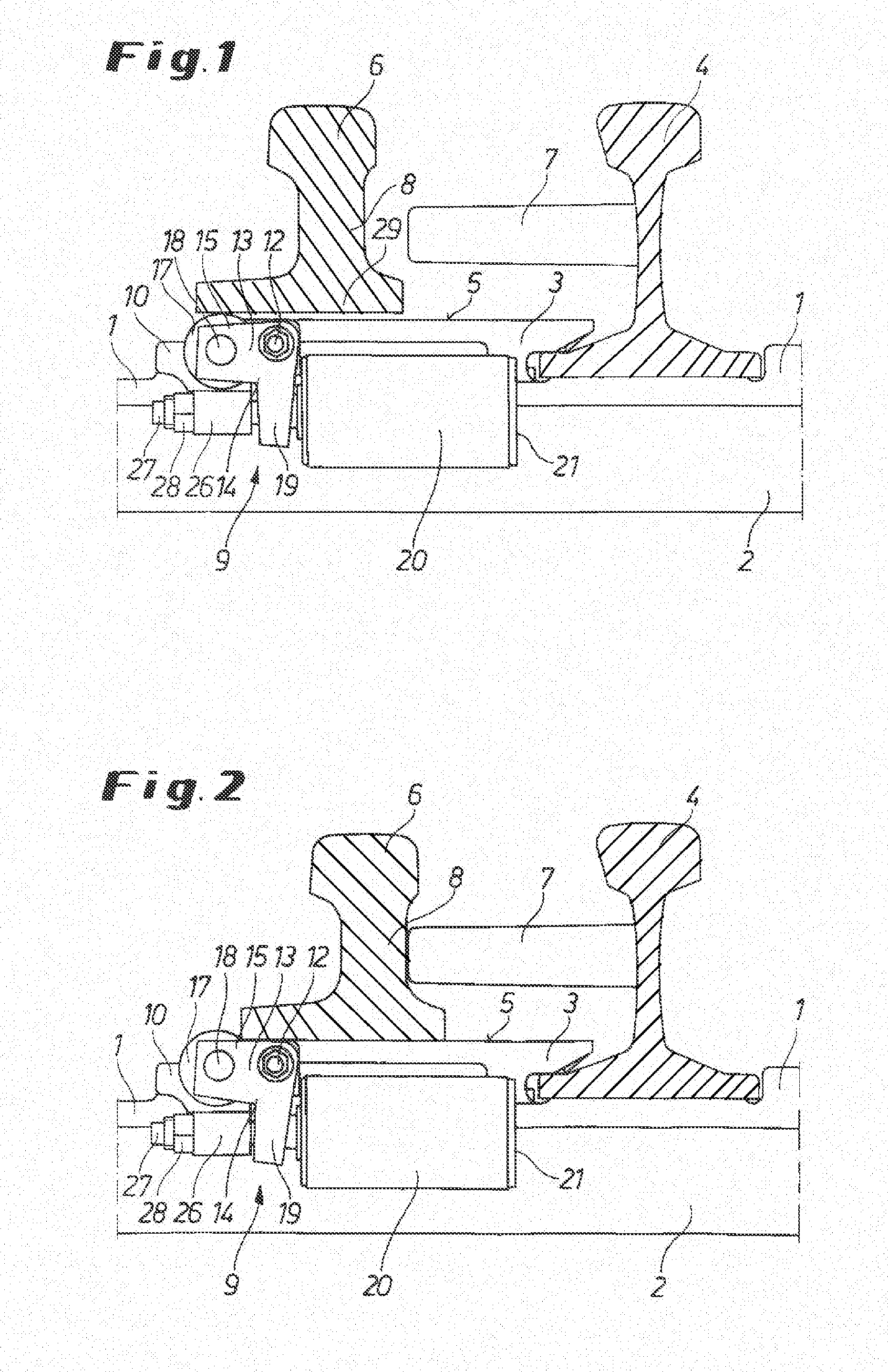
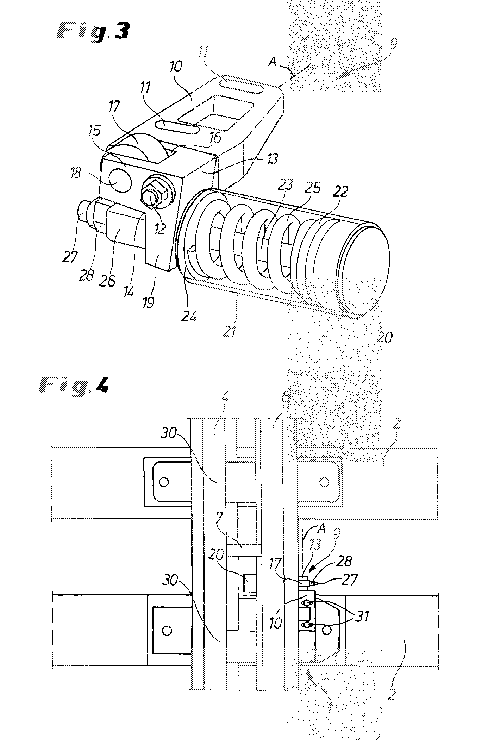
[0027]As seen in FIGS. 1, 2, and 4, one of two railroad stock rails 4 running parallel and spaced apart from each other is secured by respective standard base plates 1 to two transversely extending concrete sleepers 2, one of which is provided with a switch according to the invention. The rail base plate 1 is formed with a slide chair 3 fitting at one side with the foot of the stock rail 4 and that, on its planar upper face, forms a support face 5 for a point rail 6.

[0028]Spacers or cleats 7, one of which is shown in the drawing, project transversely from the stock rail 4 toward the point rail 6. In the switch, the point rail 6 abuts in the engaged position along the length of the switch against the stock rail 4 in a slightly curved course, i.e. at one end spaced by the support cleats 7 that abut against the point rail web 8 as shown in the FIGS. 2 and 4 and, at the other end, with the tip of the point rail 6 abutting directly against the stock rail 4.

[0029]A roller assembly 9 is pr...


PUM


Abstract

A point rail is shiftable transversely on an upper face of a rail base plate between an engaged position bearing on a longitudinally extending and fixed stock rail and a disengaged position spaced transversely of the stock rail. A roller assembly has a mounting plate securable to the rail base plate, a roller support pivotal about a support axis on the rail base plate, a roller carried on the roller support, and a spring biasing the roller upward with a predetermined spring force into a lift position with the roller projecting upward past the upper face for supporting the point rail on the roller. Thus this assembly supports the point rail and, in the engaged position, presses it against the support cleats and the stock rail and it is an integral part of one of the rail base plates.

Description

FIELD OF THE INVENTION[0001]The present invention relates to a railroad switch. More particularly this invention concerns a roller support for such a railroad switch.BACKGROUND OF THE INVENTION[0002]A typical railroad switch has a pair of point rails movable into and out of engagement with respective stock rails for diverting a train on the stock rails to a siding or other track. Each of the point rails is moved by a roller assembly comprising a support carrying at least one roller and resiliently supported on a rail base plate formed as a slide plate or slide chair. The point rail is supported on the roller at least during a switching process.[0003]Roller assemblies designed in such a manner are well known from the prior art and allow the point rail to be slightly lifted during the opening or switching process and therefore not in contact anymore with the slide chair or the slide surface of the rail base plate. In so doing, the point rail moves over a roller or rolling bodies that ...

Claims


Application Information

Patent Timeline
Patent Type & Authority Applications(United States)
IPC IPC(8): E01B7/08
CPCE01B7/02E01B7/00
Inventor RUETZEL, TILMANNMEYER, FRANKWIENTGES, BERND
Owner SCHWIHAG
Why Eureka
Try Eureka