
Method for controlling freezing capacity of a fixed-frequency freezing ac ice-water system

Inactive Publication Date: 2012-01-05
CHUNGHWA TELECOM CO LTD
View PDF18 Cites 0 Cited by
  • Summary
  • Abstract
  • Description
  • Claims
  • Application Information

AI Technical Summary

Benefits of technology

[0008]In view of the above drawbacks of the prior art, an object of the present invention is to improve the energy-saving effect of a fixed-frequency chiller by utilizing the operating characteristics of a plurality of compressors of the fixed-frequency chiller.
[0009]Another object of the present invention is to enable the compressors to operate collectively so as to increase the cooling efficiency and save electric power consumption.
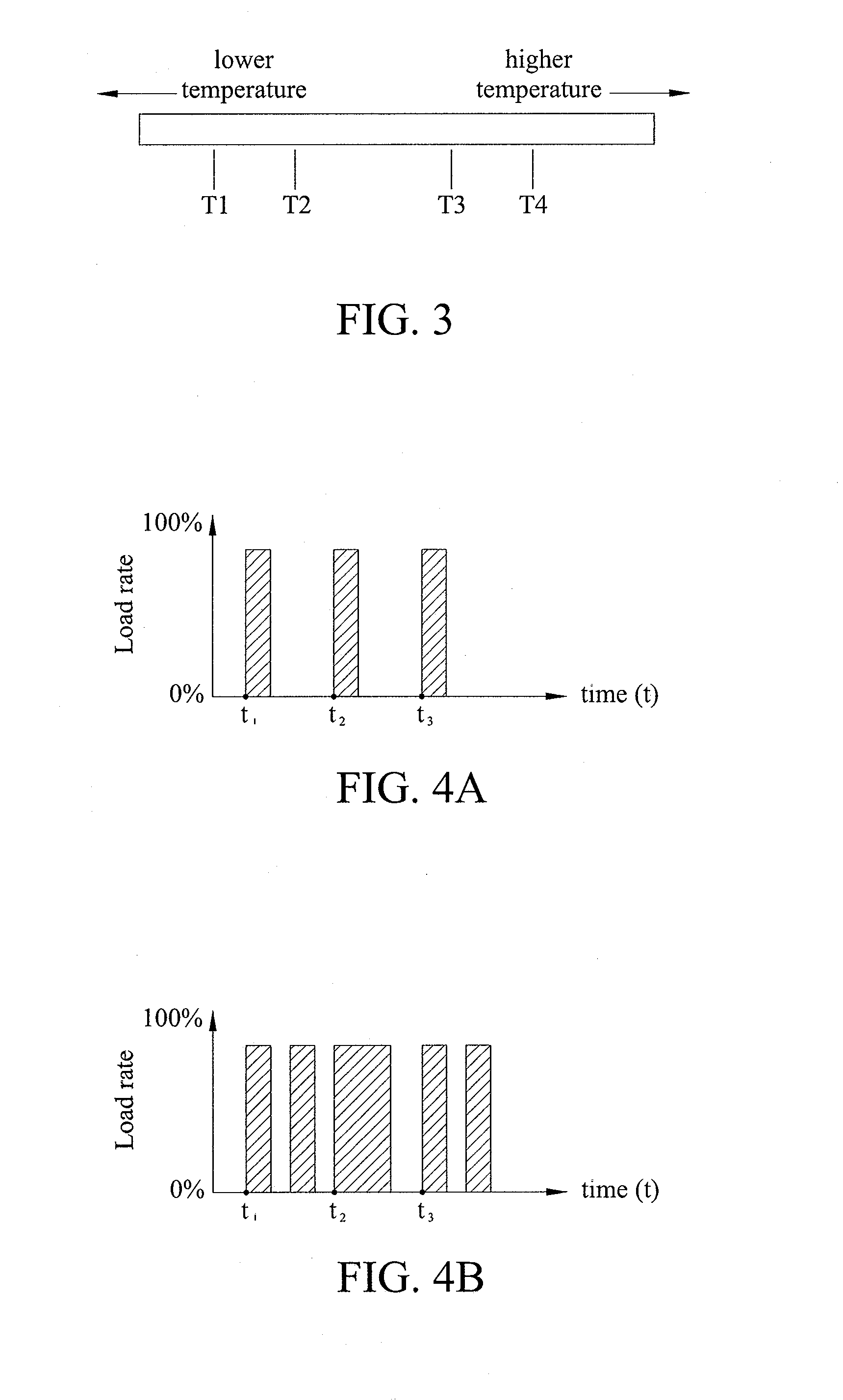
[0014]Compared with the prior art, the method of the present invention utilizes the temperature buffer difference between any two of the requirement ends to control the number of operating compressors of a fixed-frequency chiller and make each of the operating compressors have a usage rate close to 100%. The method of the present invention can be applied to an air conditioner or a chilling system with a fixed-frequency chiller so as to change the operating efficiency of the fixed-frequency chiller and reduce electric power consumption and further improve the cooling efficiency and cost-effectiveness thereof.

Problems solved by technology

In practice, a chiller usually supplies a huge freezing capacity, which thus results in high electric power consumption.
For example, a chiller in a supermarket supplies several tons to several hundreds of tons of freezing capacity, thereby resulting in high electric power consumption and high cost.
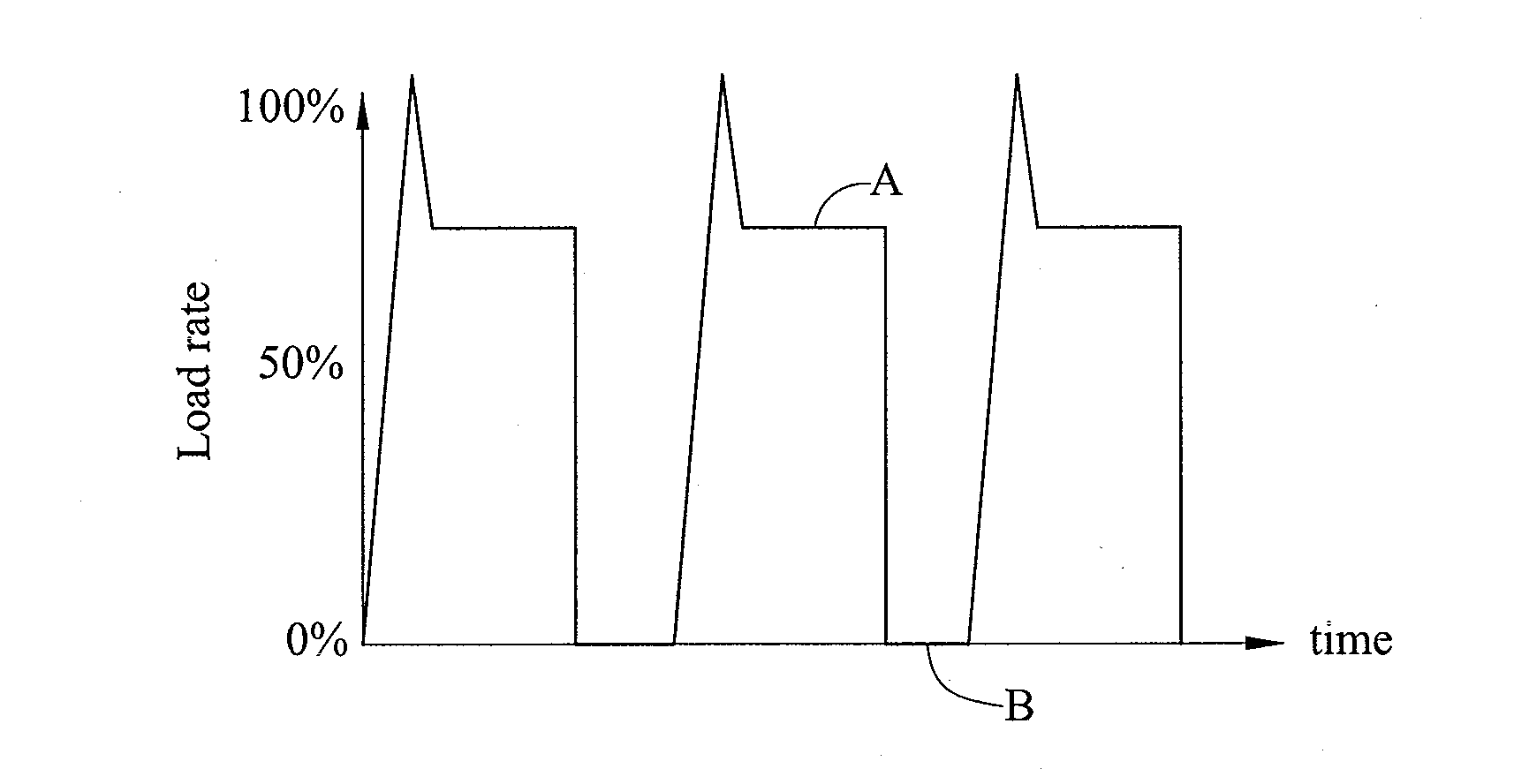
When one of the compressors of the fixed-frequency chiller starts to operate, it operates at the maximum freezing capacity and has an electric power consumption of 100% of the rated power.
However, along with continuing global warming, only using such a fixed-frequency chiller with the number of operating compressors varied according to the required total supply of frequency capacity cannot meet the high demand for carbon emission reduction.

Method used


Image

  • Method for controlling freezing capacity of a fixed-frequency freezing ac ice-water system
  • Method for controlling freezing capacity of a fixed-frequency freezing ac ice-water system
  • Method for controlling freezing capacity of a fixed-frequency freezing ac ice-water system

Examples


Embodiment Construction

[0020]The following illustrative embodiments are provided to illustrate the disclosure of the present invention, these and other advantages and effects can be apparent to those in the art after reading this specification.

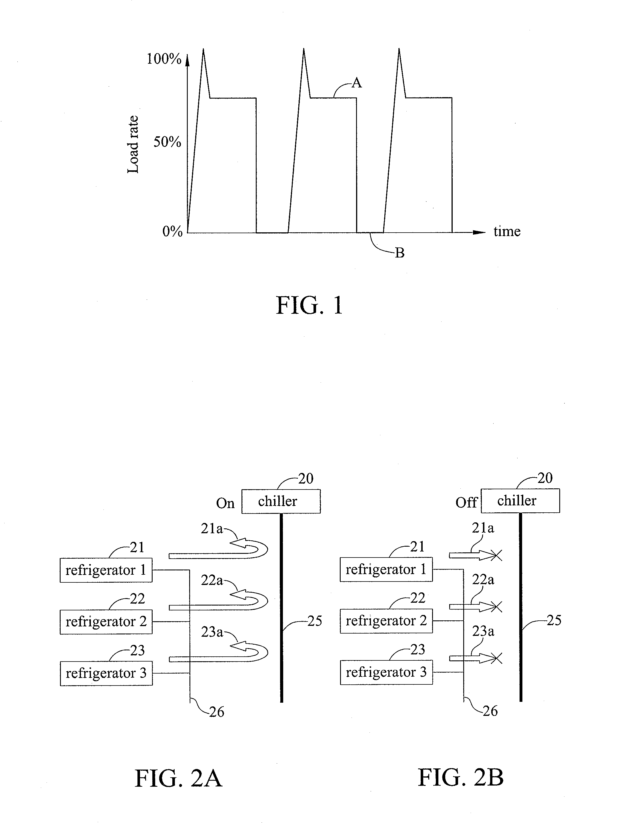
[0021]FIG. 2A shows an application structure of a method for controlling the freezing capacity of a fixed-frequency AC ice-water system, wherein the fixed-frequency AC ice-water system comprises a fixed-frequency freezing capacity supply end (chiller) 20 and a plurality of requirement ends 21, 22, 23. Referring to FIG. 2A, the supply end 20 is at ON state and heat exchanges 21a, 22a, 23a occur between the requirement ends 21, 22, 23 and the supply end 20 through an ice-water pipeline 25 so as to achieve desired cooling effects. Referring to FIG. 2B, the supply end 20 is at OFF state and no heat exchange occurs between the requirement ends 21, 22, 23 and the supply end 20.

[0022]In the present invention, the freezing capacity supplied by the supply end 20 is defined a...


PUM


Abstract

A method for controlling the freezing capacity of a fixed-frequency freezing AC ice-water system, by using temperature buffer difference of individual requirement ends to control the number of operating compressors in a fixed-frequency chiller and make each of the operating compressors have a usage rate close to 100%. Further, various operating procedures are defined for the requirement ends and each of the operating procedures has an individually defined high-low temperature range such that the freezing capacity supply cycle or startup cycle of the fixed-frequency chiller can be adjusted by using the high-low temperature ranges of the operating procedures as temperature buffer strips, thereby allowing the compressors in the fixed-frequency chiller to operate collectively in order to save energy.

Description

BACKGROUND OF THE INVENTION[0001]1. Field of the Invention[0002]The present invention relates generally to methods for controlling the freezing capacity of freezing AC ice-water systems, and more particularly, to a method for controlling the freezing capacity of a fixed-frequency freezing AC ice-water system.[0003]2. Description of Related Art[0004]Generally, requirement ends in business places or office buildings for temperature control (e.g. air conditioners, central air conditioning systems, freezers, refrigerators etc.) require large power output to achieve a sufficient cooling effect. Several requirement ends in a business place are usually connected to a rear end chiller and exchange heat with the chiller for achieving desired cooling effects. For example, freezers and refrigerators in a supermarket or a warehouse are connected to a rear end chiller so as to allow heat exchange to occur therebetween through a cooling fluid provided by the chiller, thereby achieving freezing an...

Claims


Application Information

Patent Timeline
IPC IPC(8): F25C1/00
CPCF25D29/00F25B2400/06
Inventor CHEN, SHYANG-YIHWANG, YU-HUANHSU, CHEN-KUNPAN, MING-HSIENCHEN, PIN-CHUANYANG, YA-RULIN, YAN-SHAO
Owner CHUNGHWA TELECOM CO LTD
Learn More