
Adaptive cancellation of multi-path interferences

a multi-path interference and adaptive cancellation technology, applied in the field of interference cancellation systems and methods, to achieve the effect of reducing or eliminating unwanted signals arriving

Active Publication Date: 2011-12-29
HARRIS CORP
View PDF5 Cites 75 Cited by
  • Summary
  • Abstract
  • Description
  • Claims
  • Application Information

AI Technical Summary

Benefits of technology

[0019]It is an object of the present invention to provide an interference cancellation system which is adapted to minimize or eliminate unwanted signals arriving at a radio receiver through multiple propagation paths.
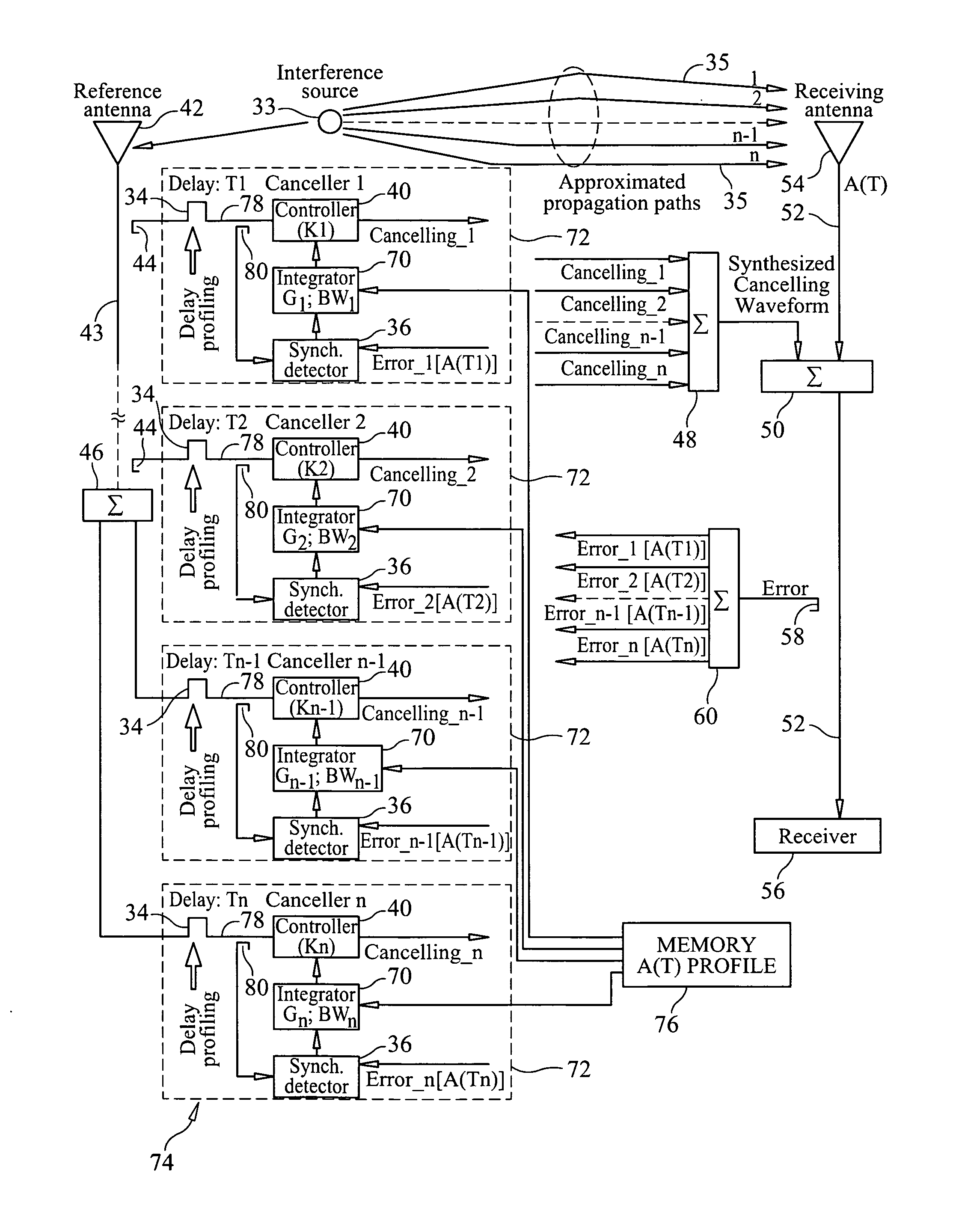
[0021]It is yet a further object of the present invention to provide an interference cancellation system and method which enhance the degree of adaptive cancellation of multi-path interferences by creating a time-delay domain, gain-bandwidth profile within the cancellation closed loop responses of multiple canceller systems that are coherent with the time-delay domain intensity trends of the interference propagation paths of the interference signal to the receiving antenna.
[0022]It is yet a further object of the present invention to provide a system and method for cancelling multi-path interference signals which provide improved interference cancellation in the receive line of a radio receiver.

Problems solved by technology

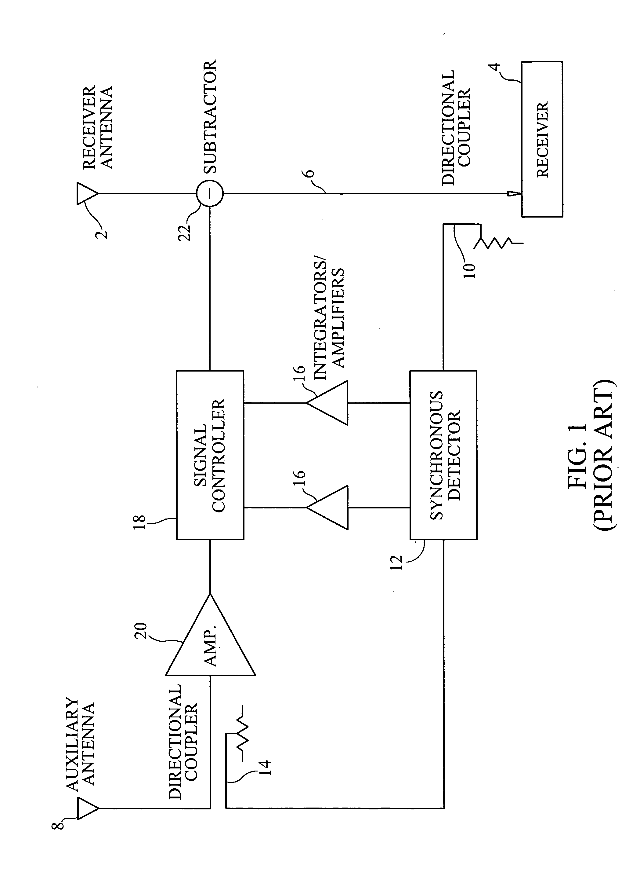
A problem with the conventional adaptive interference cancellation system shown in FIG. 1 is when the interference signal follows multiple paths, which can occur due to multiple reflections or the like.

Method used


Image

  • Adaptive cancellation of multi-path interferences
  • Adaptive cancellation of multi-path interferences
  • Adaptive cancellation of multi-path interferences

Examples


Embodiment Construction

[0033]In order to facilitate a full understanding of the invention, reference should first be made to FIG. 3 of the drawings, which is a three dimensional graph portraying a typical multi-path intensity profile A(T) of an interference signal in the time-delay and frequency domains as affected by the various propagation paths 35 which the interference signal takes. It should be noted that like reference numbers used herein and shown in the drawings refer to the same or similar components or items. An interference signal emanating from a source 33 may follow multiple paths 35 due to reflections caused by atmospheric conditions, buildings, structures or the like, to a receive antenna 54 of a radio receiver system. A typical time-spreading of the interference signal, arriving from its source to a receive antenna 54 through a number of propagation multi-paths 35 viewed in the time-delay and frequency domains, is depicted in FIG. 3. As can be seen from FIG. 3, the multi-path intensity (e....


PUM


Abstract

A multi-path signal interference cancellation system cancels multiple time delayed signal components of a multi-path interference signal received by a receive antenna and carried on a receiver transmission line of a radio receiver system. The interference cancellation system includes a plurality of adaptive interference canceller circuits, each of which has a synchronous detector, a signal controller and an integrator as essential parts of closed control loops defined by the canceller circuits. The integrator has gain and bandwidth characteristics associated therewith which are adjustable to adjust the gain and bandwidth of each closed control loop. An intensity profile of the multi-path interference signal is generated and stored in a memory. An intensity profile signal from the memory is provided to the integrator of each adaptive interference canceller circuit to adjust the gain and bandwidth of the integrator and the loop in which it is situated to maximize the error detection residual signal-to-noise ratio of each adaptive interference canceller circuit. Each adaptive interference canceller circuit generates a cancellation signal from which a synthesized cancellation signal is generated and effectively injected onto the receiver transmission line to cancel the multiple time delayed signal components of the multi-path interference signal carried thereon so that the radio receiver of the radio receiver system only receives a desired signal.

Description

BACKGROUND OF THE INVENTION[0001]1. Field of the Invention[0002]The present invention relates to interference cancellation systems and methods, and more particularly relates to interference cancellation systems and methods for minimizing or eliminating interference in radio receivers due to unwanted signals. Even more specifically, this invention relates to an interference cancellation system and method for minimizing an interfering signal which arrives at different times at the radio receiver through multi-paths due to reflections or the like.[0003]2. Description of the Prior Art[0004]An adaptive interference cancellation system cancels interferences in a receive line by employing synchronous detectors, such as vector demodulators, signal controllers, such as vector modulators, and integrators, as the central elements of a closed control loop within the cancellation system that require no a priori knowledge of the interference signal characteristics, leaving the desired signal almo...

Claims


Application Information

Patent Timeline
IPC IPC(8): H04B1/10
CPCH04B1/1081H04B1/1036
Inventor BORNAZYAN, GEVORK GEORGE
Owner HARRIS CORP
Learn More