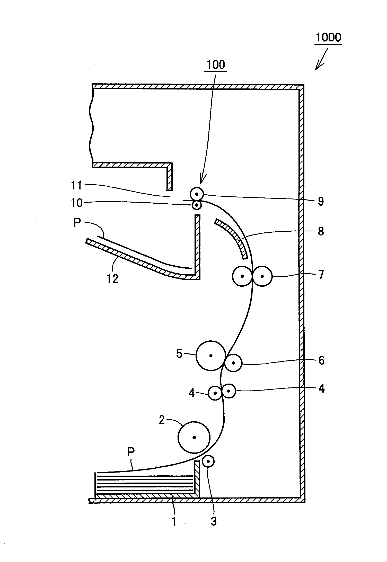
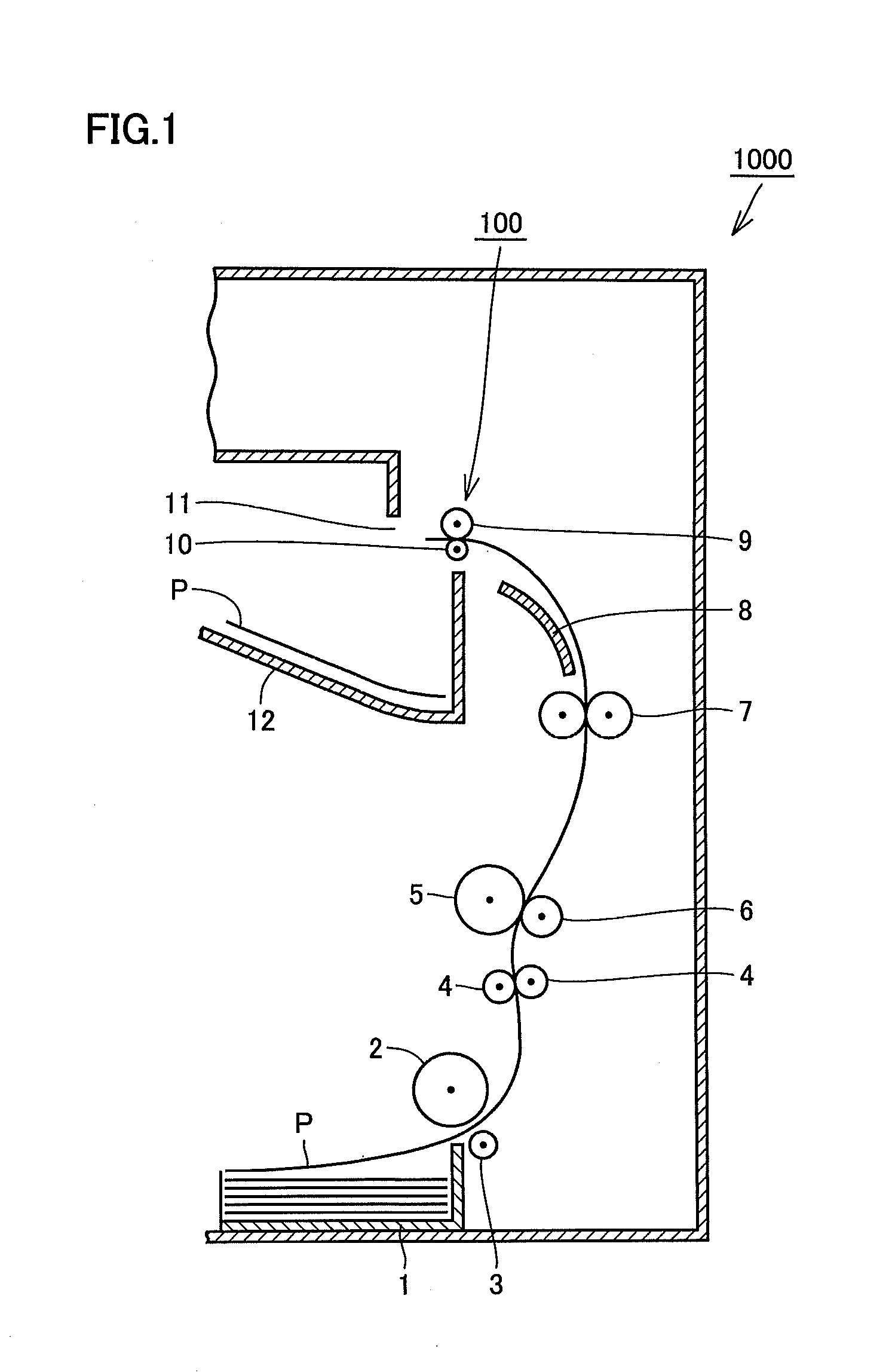
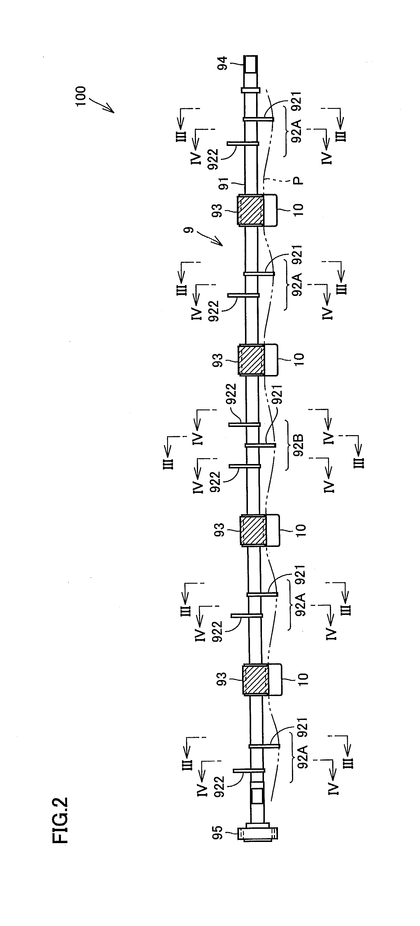
Sheet discharge roller and image forming apparatus

a technology of discharge roller and discharge plate, which is applied in the directions of transportation and packaging, thin material handling, and delivery of articles, to achieve the effect of reducing assembly efficiency and increasing rigidity of discharged sheets

Active Publication Date: 2011-12-22
KONICA MINOLTA BUSINESS TECH INC
View PDF6 Cites 1 Cited by
  • Summary
  • Abstract
  • Description
  • Claims
  • Application Information

AI Technical Summary

Benefits of technology

[0014]Accordingly, the invention has been made for overcoming the above problem, and an object of the invention is to provide a sheet discharge roller and an image forming apparatus having structures that sufficiently maintain a function of increasing rigidity of discharged sheets without lowering assembling efficiency.

Problems solved by technology

However, it causes the following problems.

Method used


Image

  • Sheet discharge roller and image forming apparatus
  • Sheet discharge roller and image forming apparatus
  • Sheet discharge roller and image forming apparatus

Examples


second embodiment

[0073]Referring to FIGS. 15 to 18, description will be made on the sheet discharge roller in a second embodiment. This embodiment differs from the first embodiment only in structure of a rigidity increasing portion 92C employed in the sheet discharge roller. Therefore, only the structure of rigidity increasing portion 92C in this embodiment will be specifically described below.

[0074]Rigidity increasing portion 92C has plate members 931, 932 and 933.

[0075]Referring to FIG. 16A, plate member 931 has a form substantially corresponding to one of pieces obtained by circumferentially trisecting a circular plate. In the figure, it has a sectorial portion R11 on an upper side with respect to rotation shaft 91, and also has plate-like portions R12 that are located on the circumferentially opposite sides, respectively.

[0076]Referring to FIG. 16B, plate member 932 has a form substantially corresponding to one of pieces obtained by circumferentially trisecting a circular plate. In the figure, i...

third embodiment

[0083]Referring to FIGS. 19, 20A and 20B, a sheet discharge roller of a third embodiment will be described below. This embodiment differs from the first embodiment already described only in the structure of a rigidity increasing portion 92D employed in the sheet discharge roller. Therefore, the structure of rigidity increasing portion 92D in this embodiment will be specifically described below.

[0084]Rigidity increasing portion 92D has the same basic structure as rigidity increasing portion 92A already described in connection with the first embodiment, and has plate members 921 and 922 having substantially the same form. There is a difference that each of plate members 921 and 922 is provided at its outer periphery with radially protruding convex portions 921t.

[0085]In this embodiment, each of plate members 921 and 922 is provided at its outer periphery with three convex portions 921t, but the number of convex portions 921t is not restricted to three. Other structures of rigidity in...


PUM

PropertyMeasurementUnit
distanceaaaaaaaaaa
outer diameteraaaaaaaaaa
rigidityaaaaaaaaaa

Abstract

In a sheet discharge roller, a transportation roller includes a roller portion formed integrally on a rotation shaft, and an annular elastic member attached to a surface of the roller portion, each of rigidity increasing portions includes a plurality of plate members axially spaced from each other by a predetermined distance, and the plurality of plate members have forms each obtained by circumferentially dividing a circular plate, respectively, are arranged in positions circumferentially shifted from each other, respectively, and thereby exhibit an outer periphery of a substantially circular form when viewed in the axial direction.

Description

[0001]This application is based on Japanese Patent Application No. 2010-138056 filed with the Japan Patent Office on Jun. 17, 2010, the entire content of which is hereby incorporated by reference.BACKGROUND OF THE INVENTION[0002]1. Field of the Invention[0003]The present invention relates to a sheet discharge roller employed in a sheet exit port of an image forming apparatus as well as an image forming apparatus provided with the sheet discharge roller.[0004]2. Description of the Related Art[0005]For improving sheet discharging performance for discharging paper sheets, processing of increasing rigidity of the paper sheet is performed by slightly curving the paper sheet in a direction (i.e., a widthwise direction of the paper sheet) perpendicular to a sheet discharging direction when the paper sheet is discharged from an exit port of an image forming apparatus. As a method for increasing rigidity of the paper sheet, there has been a method in which a rigidity increasing portion indep...

Claims


Application Information

Patent Timeline
Patent Type & Authority Applications(United States)
IPC IPC(8): B65H29/20
CPCB65H29/125B65H29/14B65H2301/51214B65H2301/5122B65H2404/1112B65H2404/1115B65H2404/1118B65H2404/1321B65H2801/06B65H29/70B65H2402/60
Inventor NAKAMURA, SHIGEO
Owner KONICA MINOLTA BUSINESS TECH INC
Why Eureka
Try Eureka