Push switch
a push switch and push plate technology, applied in the field of push plates, can solve the problems of /b> damage, /b> breakage, and the elastic engagement member b> will be damaged, and achieve the effect of preventing excessive force, effectively preventing damage to the switch 40, and effectively preventing damag
- Summary
- Abstract
- Description
- Claims
- Application Information
AI Technical Summary
Benefits of technology
Problems solved by technology
Method used
Image

Examples
first embodiment
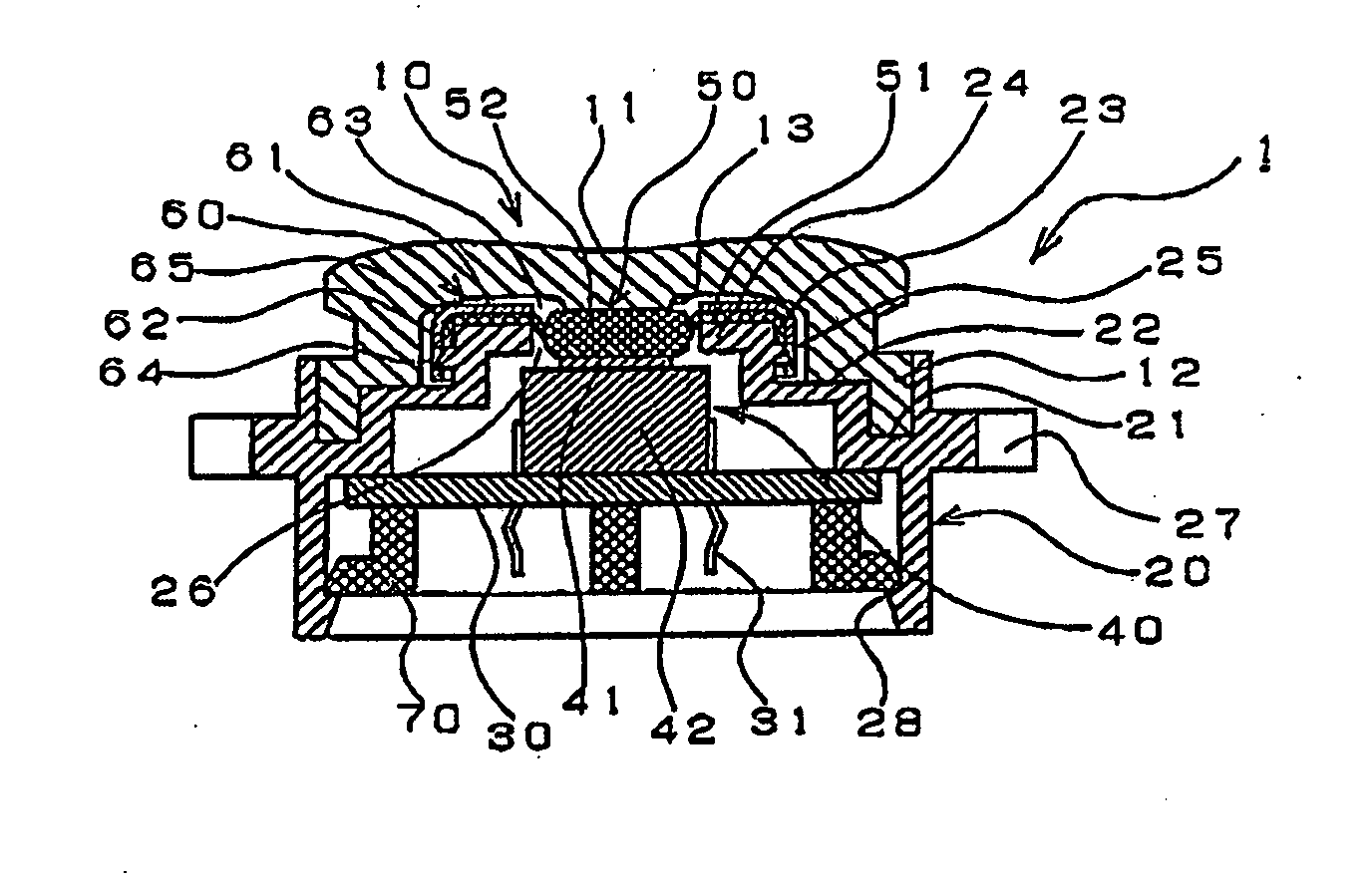
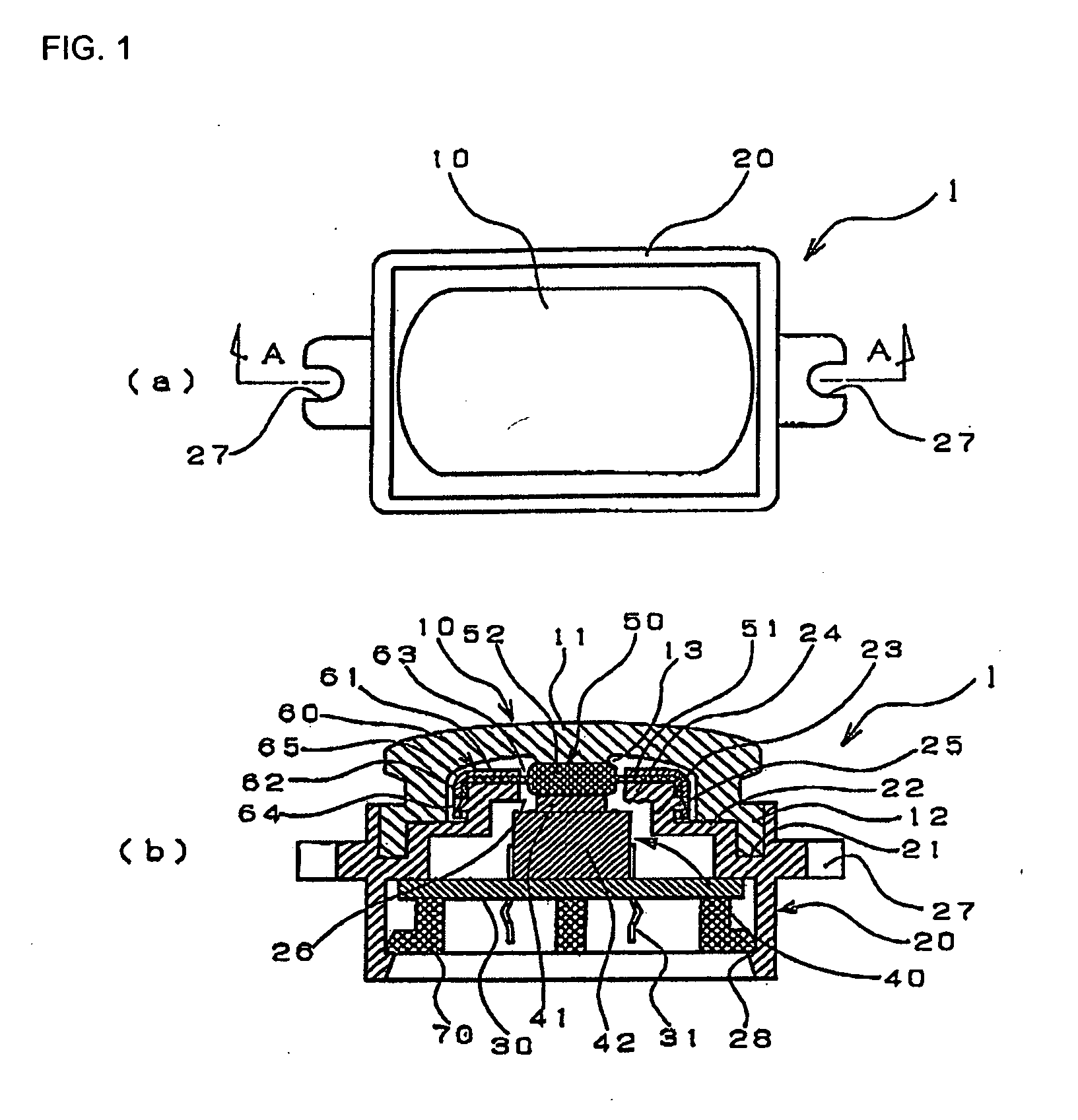
[0022]FIG. 1 shows a push switch 1 according to this example, wherein FIG. 1(a) is a plan view, and FIG. 1(b) is a sectional view along line of A-A in FIG. 1(a).
[0023]The push switch 1 of this example is mounted in a vehicle door handle device, which is not shown in the drawing. When a user operates a door lock device, a cap member 10 of the push switch 1 that is exposed by the vehicle door handle device is pushed, whereby the door can be locked or unlocked.
[0024]The push switch 1 according to this example comprises a cap member 10, a case 20, a switch board 30, a switch 40, a seal member 50, a seal cover 60 and a stopper 70.
[0025]The cap member 10 is formed from an elastically flexible resin, such as rubber, and comprises a substantially rectangular top actuation wall 11 and, descending vertically from the peripheral edge thereof, a peripheral side wall 12, having an opening at the bottom. Furthermore, an actuation protrusion 13 is provided on the bottom of the top actuation wall 1...
second embodiment
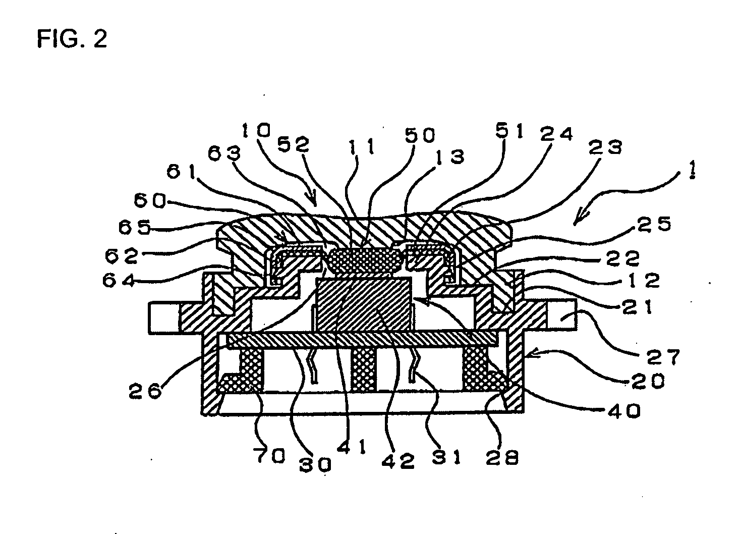
[0048]FIG. 3 is a sectional view of a push switch 1A according to this example. In FIG. 3, identical reference numerals have been used for components identical to those in the first mode of embodiment, and redundant description of the same has been omitted.
[0049]The points in this example that differ from the first mode of embodiment are that a corner portion 29 at the intersection between the side wall 23 and the top wall 24 of the case 20 is formed as a curve, and the seal member 50 is mounted affixed to the side wall 23 and the top wall 24, without using the seal cover 60 shown in FIG. 1.
[0050]With the push switch 1A according to this example, the top face of the button part 52 faces the actuation protrusion 13, which is provided on the inner face of the cap member 10, and arranged so as to be in proximity to, or in contact with, the actuation protrusion 13. Furthermore, the bottom face of the button part 52 faces the actuation part 41 of the switch 40, via the opening 26 that is...
PUM
 Abstract
Description
Claims
Application Information
 - R&D
- Intellectual Property
- Life Sciences
- Materials
- Tech Scout
- Unparalleled Data Quality
- Higher Quality Content
- 60% Fewer Hallucinations
Browse by: Latest US Patents, China's latest patents, Technical Efficacy Thesaurus, Application Domain, Technology Topic, Popular Technical Reports.
© 2025 PatSnap. All rights reserved.Legal|Privacy policy|Modern Slavery Act Transparency Statement|Sitemap|About US| Contact US: help@patsnap.com