
Display device

Active Publication Date: 2011-12-15
SAMSUNG DISPLAY CO LTD
View PDF5 Cites 7 Cited by
  • Summary
  • Abstract
  • Description
  • Claims
  • Application Information

AI Technical Summary

Benefits of technology

[0016]In another aspect, a red color filter or a green color filter may include a coloring agent that absorbs light having wavelengths of about 420 nm to about 470 nm. Thus, deterioration of color reproducibility of a display device, which includes a light emitting unit converting a blue light generated by a light source into a white light and emitting the white light to an exterior of the light emitting unit, may be prevented. When a display device includes a cold cathode fluorescent lamp (CCFL) as a light source, light generated by the CCFL does not include much light having wavelengths of about 420 nm to about 470 nm. Therefore, color mixture is not a significant problem when the light generated by such a light source passes through a red color filter or a green color filter. The white light emitted by the light emitting unit including a blue light emitting diode, however, includes light having wavelengths of about 420 nm to about 470 nm. Thus, a significant color mixture problem may result. However, the display device provided herein includes a coloring agent that absorbs light having wavelengths of about 420 nm to about 470 nm, thereby optimizing color reproducibility of a red color filter and a green color filter, preventing the color mixture problems, and maintaining a brightness substantially equal to a display device that does not include the coloring agent.

Problems solved by technology

However, the color reproducibility of the display device may be affected by a light source spectrum, which varies according to the type of light source used in the light providing assembly, as well as the coloring agent used in the color filters.
Thus, when the type of light source used in the light providing assembly is changed, the light source spectrum is also changed, which can result in deterioration of the color reproducibility of the display device.
Therefore, when a color filter that has been used with a conventional light providing assembly using a CCFL as a light source is used with a light providing assembly using an LED as a light source, the color reproducibility of the display device may be deteriorated.

Method used


Image

  • Display device
  • Display device
  • Display device

Examples


Embodiment Construction

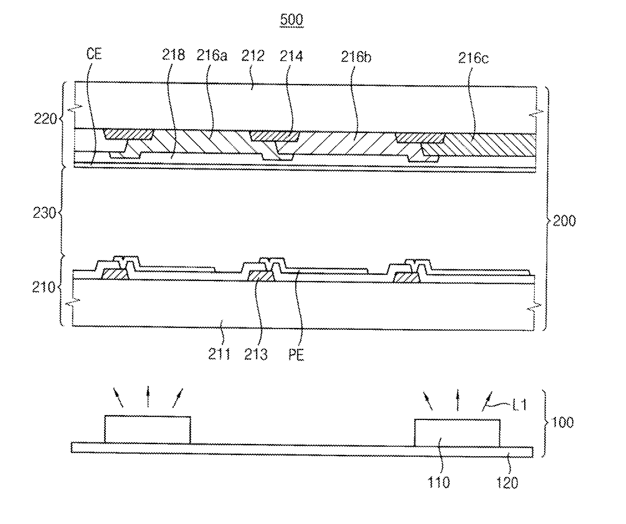
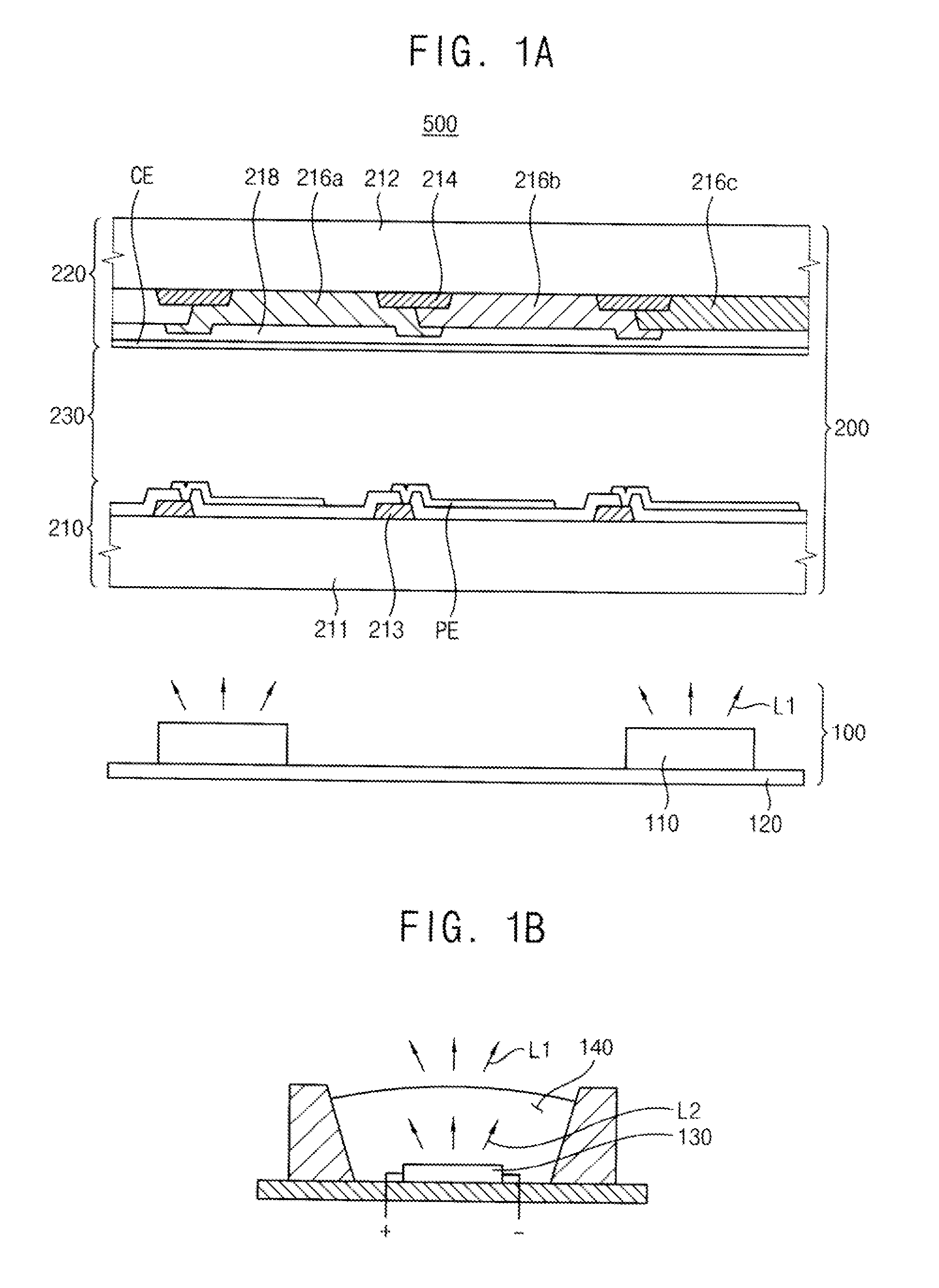
[0025]FIG. 1A is a cross-sectional view illustrating a display device according to an example embodiment.

[0026]Referring to FIG. 1A, a first display device 500 includes a first light providing assembly 100 and a first display panel 200.

[0027]The first light providing assembly 100 includes a light source unit 110 that generates light. The light source unit 110 is mounted on a circuit board 120 that provides a light source driving signal to the light source unit 110. The light source unit 110 provides a white light L1 to the first display panel 200. The light source unit 110 will be more fully explained below with reference to FIG. 1B.

[0028]The first light providing assembly 100 may further include conventional optical sheets and / or optical plates (not shown) disposed between the light source unit 110 and the first display panel 200. The optical sheets and / or optical plates diffuse and condense the light generated by the light source unit 110 to effectively direct uniform light toward...


PUM


Abstract

A display device includes a light emitting unit and a display panel including a first color filter. The light emitting unit includes a light source generating a blue light, and a light-converting part converting the blue light into a white light and emitting the white light to an exterior. The first color filter, through which the white light passes, includes a first coloring agent that absorbs about 95% to about 100% of light having wavelength of about 420 nm to about 470 nm in the white light. Thus, a color reproducibility of the display device may be improved.

Description

[0001]This application claims priority to Korean Patent Applications No. 2010-0054999, filed on Jun. 10, 2010, and all the benefits accruing therefrom under 35 U.S.C. §119, the contents of which are herein incorporated by reference in their entirety.BACKGROUND OF THE INVENTION[0002]1. Field of the Invention[0003]Example embodiments of the present invention relate to a display device. More particularly, example embodiments of the present invention relate to a display device employing a light emitting diode (LED).[0004]2. Description of the Related Art[0005]In general, a liquid crystal display (LCD) device includes a display panel and a light providing assembly. An image is displayed on the LCD device when light from the light providing assembly shines through the display panel. The display panel includes a first substrate including a switching device driving a pixel, and a second substrate facing the first substrate. A liquid crystal layer is interposed between the first and second s...

Claims


Application Information

Patent Timeline
IPC IPC(8): G02F1/1335
CPCC09K11/06C09K2211/1029C09K2211/188G02F1/133514Y02B20/181G02F2001/133614H01L51/0081H01L51/0082G02F1/133603Y02B20/00G02F1/133614H10K85/326H10K85/324C09B45/26C09B45/32G02F1/133609
Inventor LEE, YUI-KUHUH, CHULKIM, JIN-SEUKKANG, MINKANG, DONG-UKCHANG, SUN-YOUNG
Owner SAMSUNG DISPLAY CO LTD
Learn More