Method for Automatic Setting of the Rider Roll/Glue Applicator Roll Gap on a Glue Machine

a technology of automatic setting and glue machine, which is applied in the direction of mechanical means, measuring tapes, instruments, etc., can solve the problems of blistering and undesirable exterior surface of corrugated boxes, singleface webs passing through this nip may pick up too little starch or no starch at all, and the effect of reducing the production cos

Active Publication Date: 2011-11-24
BARRY WEHMILLER PAPERSYST INC
View PDF7 Cites 2 Cited by
  • Summary
  • Abstract
  • Description
  • Claims
  • Application Information

AI Technical Summary

Benefits of technology

[0014]A primary advantage of the present invention is that rider roll control is achieved with no additional mechanical hardware or mechanisms as are prevalent in prior art rider roll gap setting concepts. This ultimate simplicity means that there is no penalty related to clean up or maintenance to keep the automatic rider roll control concept of the present invention operational.
[0015]Yet another advantage of the present invention is that it can operate perfectly with no sensing of absolute value of gap or singleface web caliper as is prevalent and required by prior art technology. This means that periodic calibration of sensors is not required eliminating an operational reliability issue associated with prior art rider roll gap solutions.
[0016]It should be well understood by those skilled in the art that other embodiments of the preferred solution are possible and within the scope of this current invention. For example, the operator could enter a desired target compression of the singleface web and a suitable feedback control loop could adjust the rider roll gap to achieve variable drive current that will cause adjustment of the gap to achieve the drive current that will just yield the required compression. Additionally, the method of the present invention could include the use of any means for direct measurement of glue applicator roll motor output torque or any variable proportional to the torque for purposes of sensing and adapting to singleface web frictional drag force for purposes of controlling compression of the web between the rider roll and the glue applicator roll.
[0017]During start-up and other phases of corrugator operation involving acceleration, the glue applicator roll drive current reacts to the requirement to change the speed of the roll rather than to compression of the singleface web. According to the present invention, a filter on the drive current feedback senses the acceleration causing the gap to be latched at its current setting or an initial setting. At start-up, for example, the operator could enter the flute being run and a nominal gap setting would be selected based upon this flute type. This setting could be manually adjusted by the operator based upon his knowledge of the paper combination being run. After reaching a cruise speed, the automatic gap adjustment mode of the present invention would take over based upon settings in the drive current filter and adapt automatically to the caliper of the product being run as well as to ensuing paper changes.
[0018]Alternately, according to another aspect of the present invention, an optimal initial start-up gap setting solution would be based upon the feed forward of a singleface web caliper measured using a simple contact means. This singleface web caliper measurement would be calculated using the respective angular velocities of two idler rollers, one with the singleface web flutes down on the idler roll and the other with the singleface web wrapped such that the flutes faced outward away from the idler roll.
[0019]In yet another aspect of the present invention, this same means of measuring singleface web caliper could be used to reset the rider roll gap when a splice is made changing paper during a corrugator acceleration or deceleration phase when the rider roll gap setting would otherwise be latched. As soon as the splice enters the glue machine, as evidenced by a splice signal, the rider roll gap would adjust based upon the measured singleface web. Then, when the corrugator reached a quiescent (non-acceleration) period, the drive current feedback would be unlatched and any error associated with the gap setting based upon the sensed singleface web caliper would be corrected.

Problems solved by technology

Improper setting of the rider roll to glue applicator roll gap can create two undesirable conditions.
If the gap setting is too loose, areas along the flute tips may pick up too little starch or no starch at all.
This will result in the formation of a blistered and undesirable exterior surface of the corrugated box.
If the rider roll to glue roll gap is set too tight, the singleface web passing through this nip will be deformed and damaged.
This compression of the board past its elastic range can result in a significant loss in the mechanical strength of the corrugated box deeming it unacceptable to its application.
Significant singleface web compression also results in excessive starch application with several negative effects beyond the cost of the starch consumed.
For example, excess starch application will cause wash boarding that is difficult to print on and that shows up as undesirable striated lines through a preprinted or labeled surface.
Excessive starch application also results in increased energy consumption required to gel the starch and drive the moisture from the glue line.
This can lead to improper gap setting, particularly on corrugators that involve a lot of paper grade changes.
All of these contact and non-contact methods for singleface web flute height measurement and subsequent rider roll gap setting add complexity and require absolute calibration of the singleface web flute height sensing means as well as the rider roll gap adjustment hardware that can drift out of tune with time creating a maintenance issue.
There are several problems with the pressure loading concepts.
As a consequence it is difficult to select the desired pressure setting without getting too much or too little deflection of the flute tips.
Too little deflection can cause poor starch adhesive transfer, and too much deflection can cause permanent crush to the flute tips causing degradation in the quality of the corrugated board manufactured.
In addition, the means of sensing and controlling the pressure are complex and suffer from performance issues related to the bad environment of the glue machine.
Starch adhesive is caustic and, as is well know in the art, splashes about the glue machine contaminating operating mechanisms and requiring frequent clean up.
The contamination can affect the precision of the pressure loading mechanisms making them difficult to use in practice.

Method used


Image

  • Method for Automatic Setting of the Rider Roll/Glue Applicator Roll Gap on a Glue Machine
  • Method for Automatic Setting of the Rider Roll/Glue Applicator Roll Gap on a Glue Machine
  • Method for Automatic Setting of the Rider Roll/Glue Applicator Roll Gap on a Glue Machine

Examples


Embodiment Construction

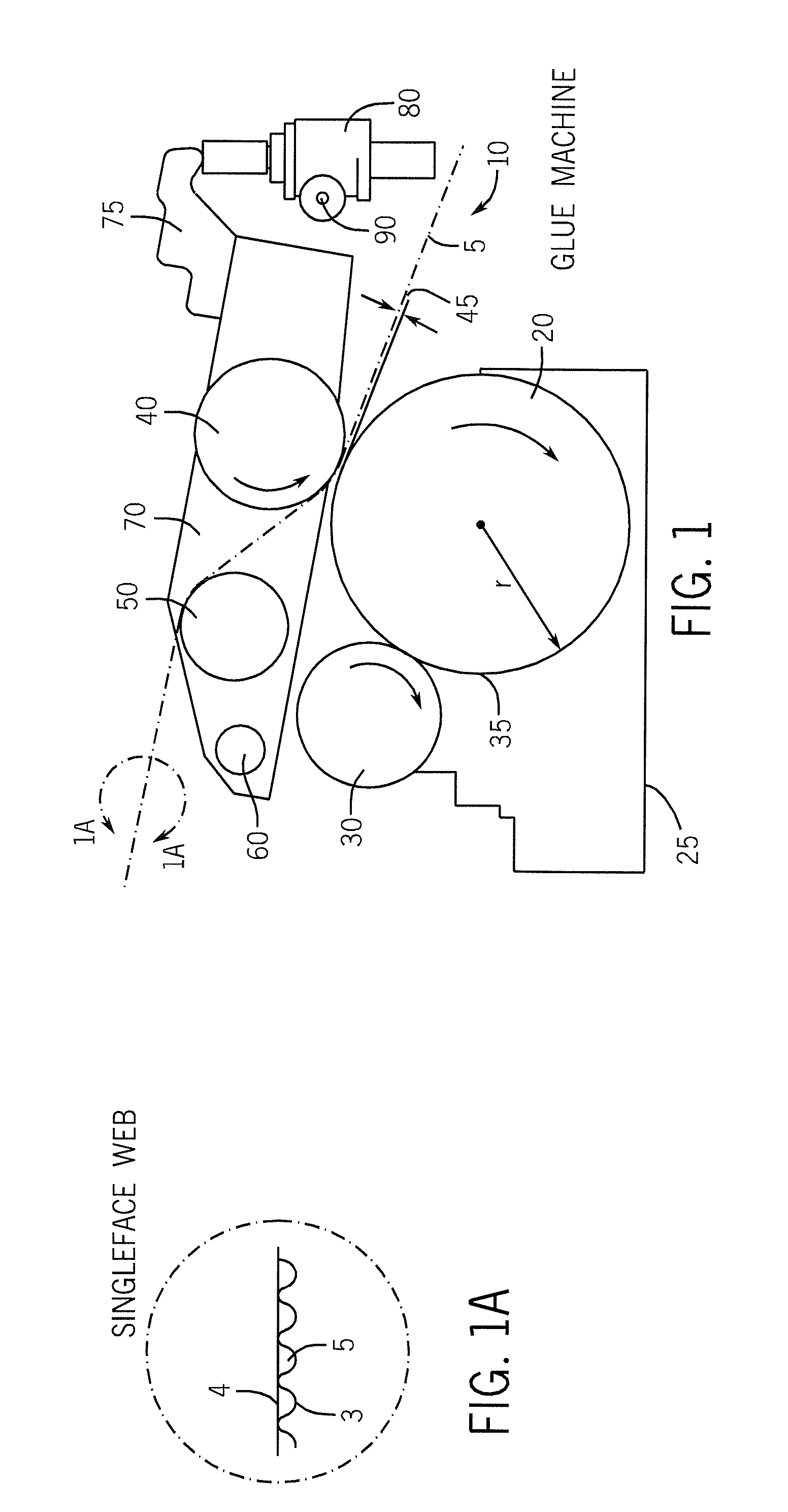
[0031]Primary and essential elements of a corrugated glue machine are shown in FIG. 1. The glue applicator roll 20 runs in a glue pan 25 where it picks up a layer of adhesive 35 that is then metered by a contra-rotating metering roll 30. It is understood by those skilled in the art that there are other means of metering the glue applicator roll glue film, for example the metering concept disclosed in U.S. Pat. No. 6,068,701.

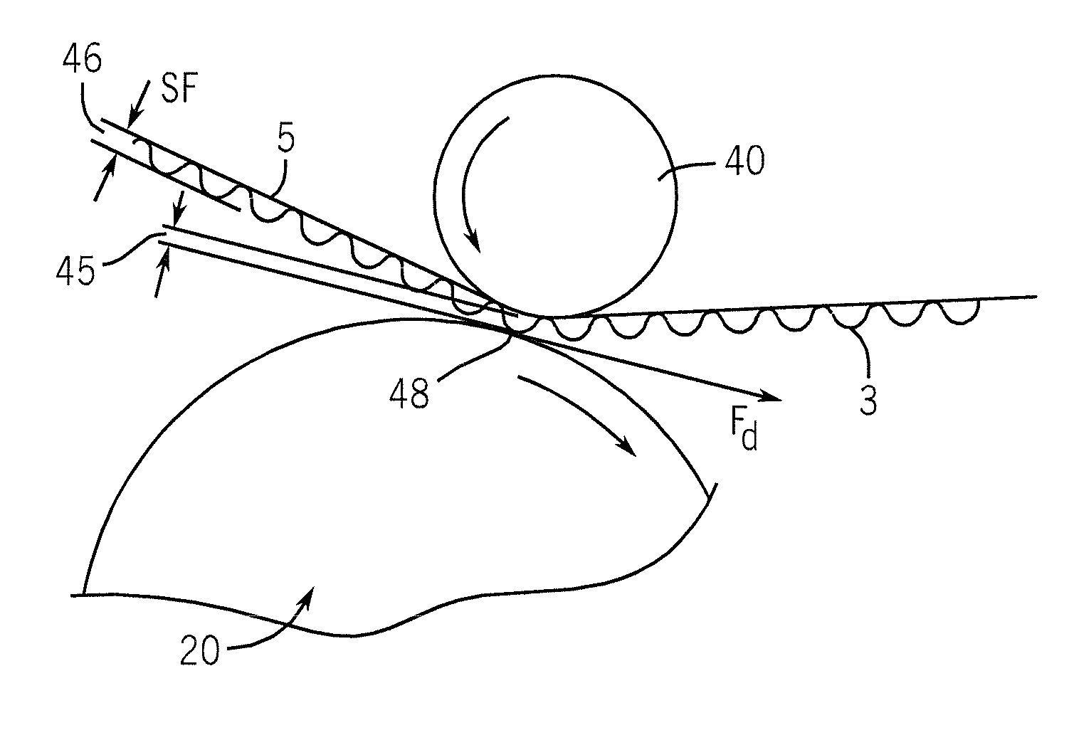
[0032]The singleface web 5 comprised of a top liner 4 and a fluted medium 3 (See FIG. 1A) that has been adhered to the top liner on upstream corrugated machinery enters the glue machine 10 around idler roll 50. Idler roll 50 is positioned such that the singleface web takes a curved wrap around rider roll 40. It is important to position the idler roll to get significant wrap so that individual flute tips of the fluted medium 3 just dip into the metered adhesive 35 as will be discussed in more detail in the description of ensuing figures.

[0033]Rider roll 40 is atta...


PUM

PropertyMeasurementUnit
thicknessaaaaaaaaaa
speedaaaaaaaaaa
drive currentaaaaaaaaaa

Abstract

A method for automatically setting the rider roll / glue applicator roll gap for the single face web on a glue machine senses a forward drag that the single face web, operating at corrugator speed, exerts on the glue applicator roll, driven at an underspeed, after bringing the flute tips of the single face web into contact with the glue applicator roll by adjusting the position of the rider roll. Changes in forward drag exerted on the glue applicator roll are monitored and related directly to glue applicator roll drive current to provide a slight compression of the single face web between the rider roll and the glue applicator roll. Preferably, the glue applicator roll uses a regenerative drive and the target drive current command in a feedback control system to cause the gap to be adjusted to achieve the desired slight compression of the web flutes and to maintain the glue applicator roll under speed.

Description

FIELD OF THE INVENTION[0001]The present invention relates to the production of corrugated board and more particularly to a novel and improved method for controlling the application of an adhesive to the flute tips of singleface web in the corrugated board manufacturing process.BACKGROUND OF THE INVENTION[0002]In the production of corrugated board a multiplicity of grades of linerboard and medium are used as well as a variety of flute formations. This requires frequent adjustment of the glue machine to maintain quality production of corrugated board. The basic concept of the present invention allows the glue machine to adapt to this changeable environment of corrugated production automatically without operator intervention required after startup of the corrugator.[0003]In the first step of corrugated board production, a machine called a singlefacer is used to flute a given grade of medium (paper) between a pair of corrugating rolls machined to a specified profile. This fluted medium ...

Claims


Application Information

Patent Timeline
Patent Type & Authority Applications(United States)
IPC IPC(8): B29C65/00B05D1/28G01B5/14B05D5/10
CPCB31F1/2818Y10T156/1025B05D5/10B31F1/2831
Inventor HIRTREITER, CHARLES M.SOFINOWSKI, JOHN R.CUMMINGS, JAMES A.
Owner BARRY WEHMILLER PAPERSYST INC
Why Eureka
Try Eureka