
Shifter assembly including display and actuation for driver control

a technology of driver control and shifter assembly, which is applied in the direction of gearing control, mechanical equipment, transportation and packaging, etc., can solve the problem of limited manual actuation of indicators

Active Publication Date: 2011-11-17
DUS OPERATING INC
View PDF24 Cites 26 Cited by
  • Summary
  • Abstract
  • Description
  • Claims
  • Application Information

AI Technical Summary

Problems solved by technology

Such manually actuated indicators are limited to only displaying the position of the transmission.

Method used


Image

  • Shifter assembly including display and actuation for driver control
  • Shifter assembly including display and actuation for driver control
  • Shifter assembly including display and actuation for driver control

Examples


Embodiment Construction

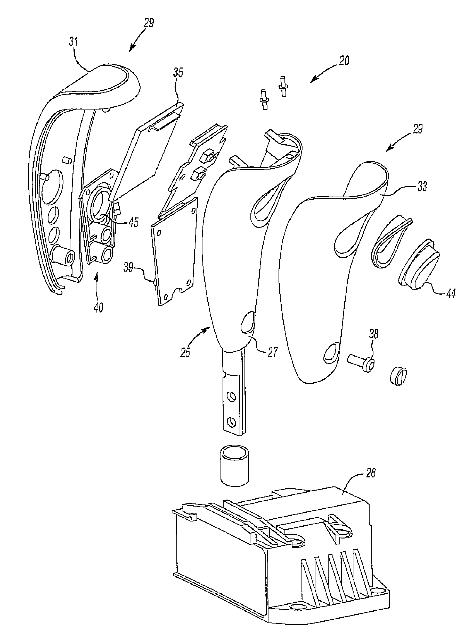
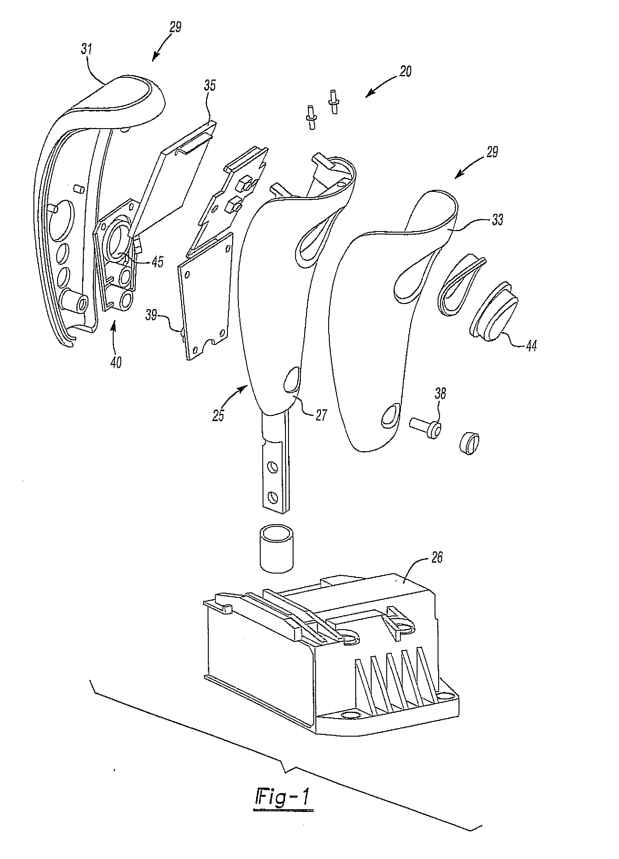
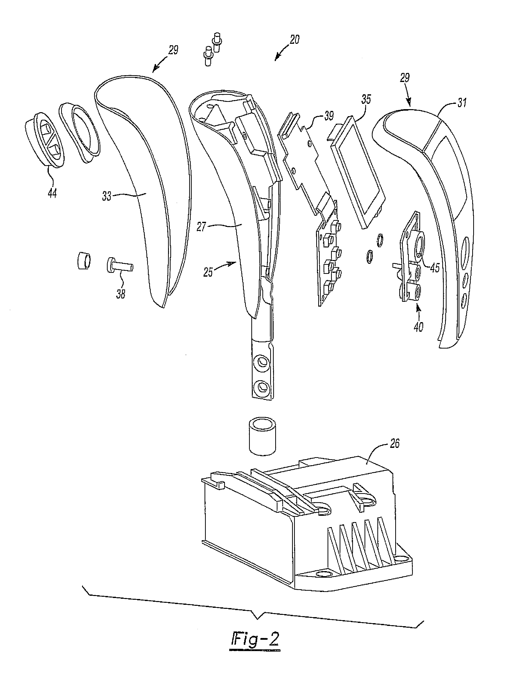
[0016]Referring to the various figures, there is shown an embodiment of a shifter assembly 20. The shifter assembly 20 includes a shift lever 25 that is connected to a shifter 26 and may be positioned in a bezel 30 and is in communication with a vehicle or transmission. The shift lever 25 includes a display 35 positioned thereon that may indicate data of the mode of the transmission, as well as various other information of a vehicle. The shifter assembly 20 may be attached to the vehicle in various manners and will vary according to the type of shifter 26 and transmission of the vehicle.

[0017]Various transmissions capable of changing a gear ratio as the vehicle moves may be utilized and may be linked with the shifter assembly 20. In one aspect, the transmission may include various types of automatic transmissions. For example, hydraulic automatic transmissions, continuously variable transmissions as well as manually controlled automatic transmissions may be utilized. Various manuall...


PUM


Abstract

A shifter assembly for a vehicle that includes a shift lever connected to a shifter and in communication with the vehicle and a transmission. A display is positioned on the shift lever indicating data of the vehicle or transmission. A start button is positioned on the shift lever and is linked with an ignition of the vehicle.

Description

RELATED APPLICATION[0001]This application claims priority of U.S. Provisional Patent Application Ser. No. 61 / 101,434 filed Sep. 30, 2008, which is incorporated herein by reference.FIELD OF THE INVENTION[0002]The invention relates to shifter assemblies and with more particularity to shifter assemblies having a display and actuation button.BACKGROUND OF THE INVENTION[0003]Generally, shifter assemblies may include a lever that moves through a gate to position the transmission of a vehicle in various states. Typically an indicator may move through a lens or cover to indicate a position of the transmission. Such manually actuated indicators are limited to only displaying the position of the transmission.[0004]Various systems in a vehicle or accessories connected to the vehicle may generate information that may be displayed to an operator. Typically that information is not displayed on a shifter. There is therefore a need in the art for a shifter that may display various information conce...

Claims


Application Information

Patent Timeline
IPC IPC(8): F16H59/04
CPCF16H59/0278Y10T74/2014F16H63/42
Inventor MCGUIRE, SEANFLYNN, CHARLES
Owner DUS OPERATING INC
Learn More