Blade row for the final stage of a steam turbine

a technology of steam turbine and final stage, which is applied in the direction of liquid fuel engines, vessel construction, marine propulsion, etc., can solve the problems of frequent erosion damage of final stage blades

Active Publication Date: 2011-11-03
GENERAL ELECTRIC TECH GMBH
View PDF2 Cites 3 Cited by
  • Summary
  • Abstract
  • Description
  • Claims
  • Application Information

AI Technical Summary

Benefits of technology

[0017]A rotating blade row for the final stage of a steam turbine has blades which each have an integrated shroud, with the shrouds, which overhang the airfoil of the blades which are adjacent in the blade row, in each case engaging in one another in the area of their trailing and leading edges. According to the invention, the shroud of each blade in the row in each case has a projection on its pressure side, which prevents droplets in the working fluid of the steam turbine from reaching the shroud fillet of the next blade in the flow direction, that is to say, the transitional zone between the suction-side shroud and the suction-side airfoil toward the leading edge. The projection shields the suction-side shroud fillet of each blade against water droplets, and against corresponding damage caused by droplets impact erosion.

Problems solved by technology

Because of the wet-steam environment, erosion damage frequently occurs on final stage blades, caused by droplets impact.

Method used


Image

  • Blade row for the final stage of a steam turbine
  • Blade row for the final stage of a steam turbine
  • Blade row for the final stage of a steam turbine

Examples


Embodiment Construction

Introduction to the Embodiments

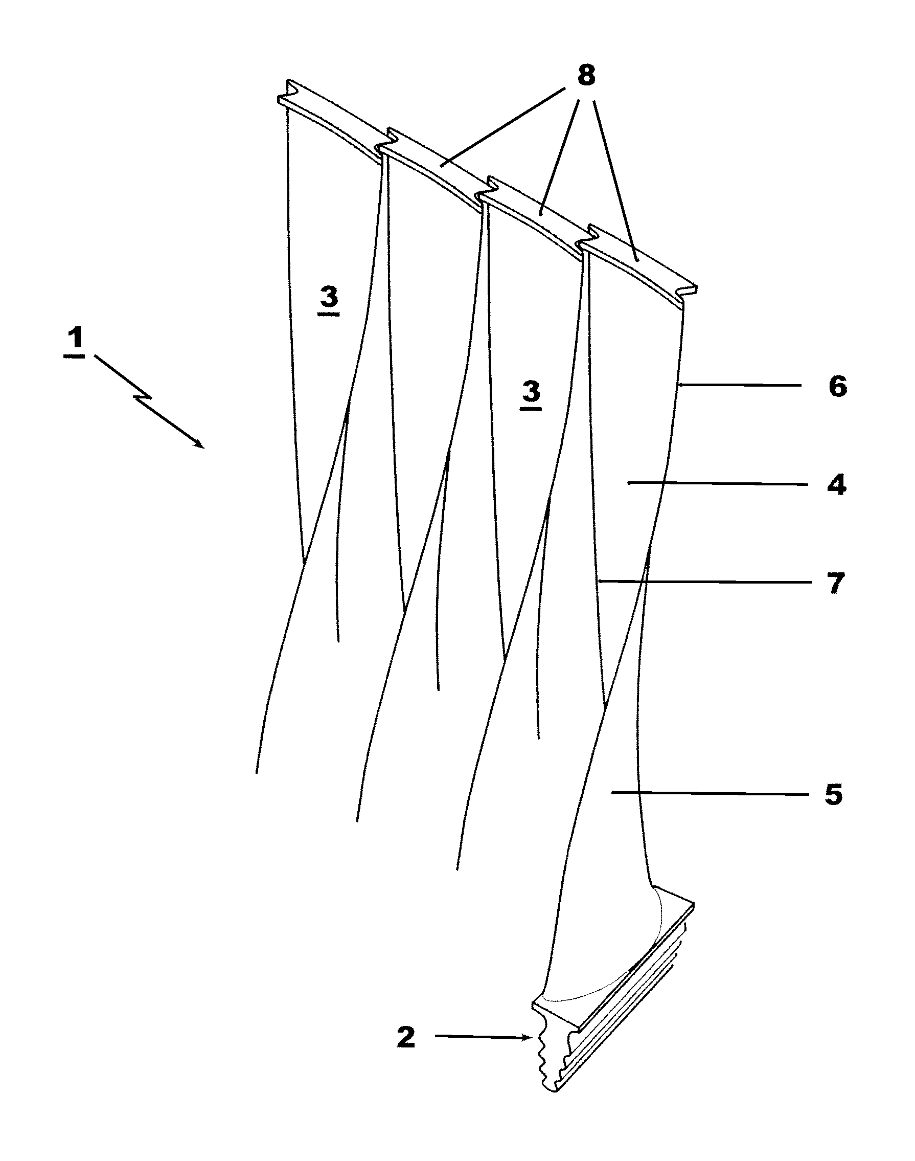
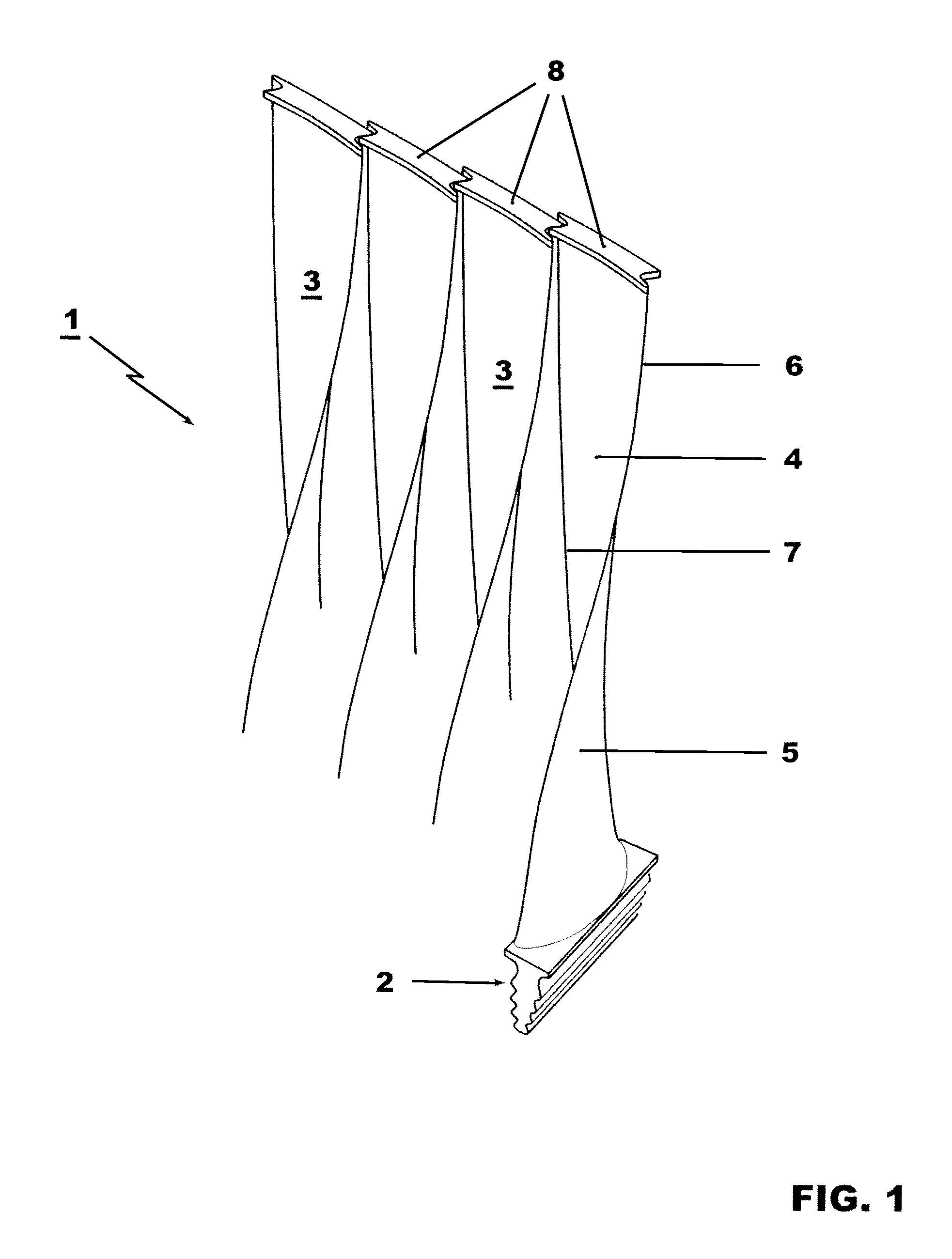
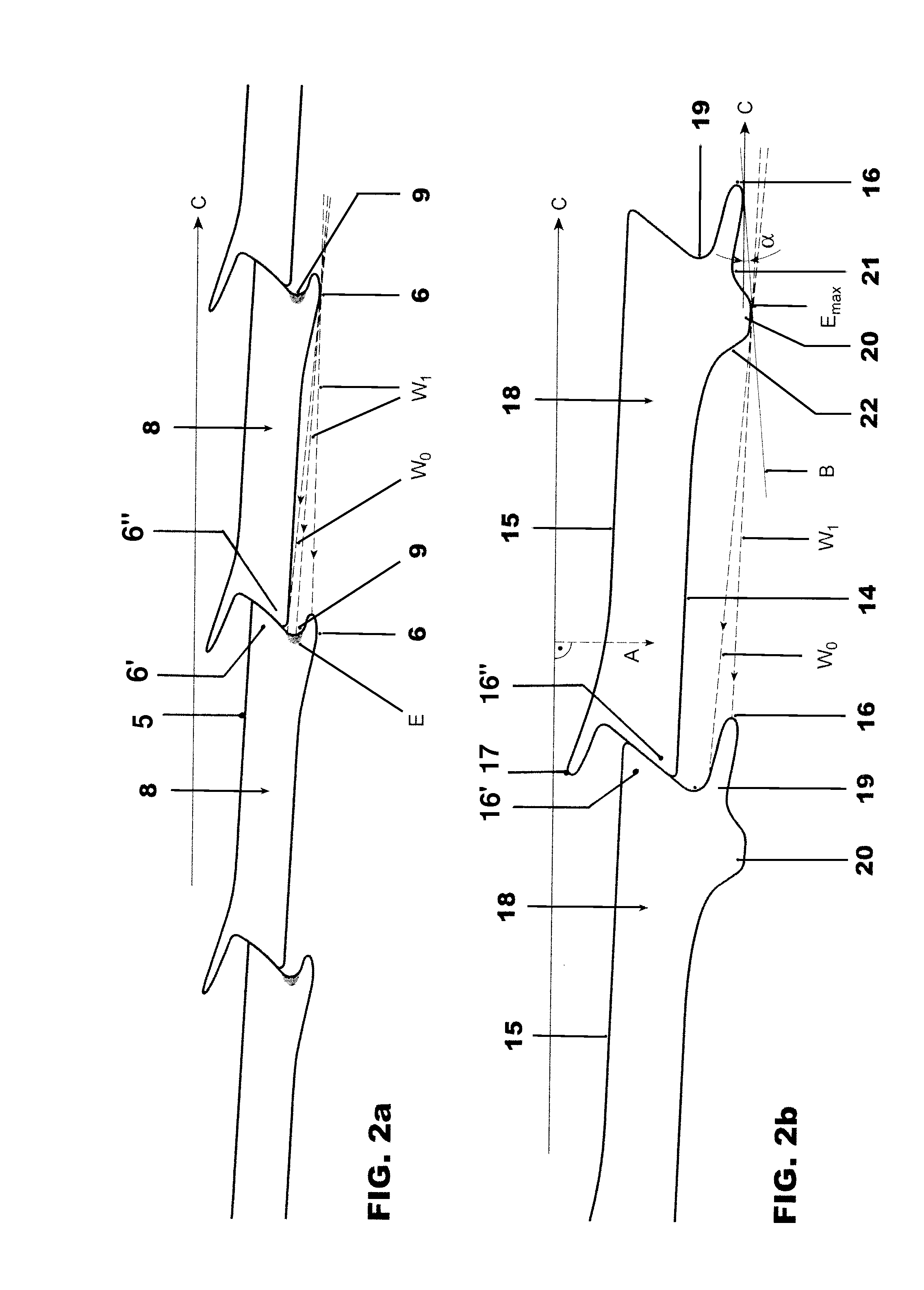
[0015]The present invention is based on the object of providing a rotating blade row for the final stage of a steam turbine, whose susceptibility to erosion damage is reduced, particularly on the shroud fillet on the suction side of the blade, that is, in the transitional zone between the suction side of the shroud and the suction side of the airfoil, toward the leading edge.

[0016]This object is achieved by a rotating blade row as claimed in the independent claim. Special embodiments of the invention are specified in the dependent claims.

[0017]A rotating blade row for the final stage of a steam turbine has blades which each have an integrated shroud, with the shrouds, which overhang the airfoil of the blades which are adjacent in the blade row, in each case engaging in one another in the area of their trailing and leading edges. According to the invention, the shroud of each blade in the row in each case has a projection on its pressure side, which pre...


PUM


Abstract

A rotating blade row is provided for the final stage of a steam turbine has blades with an integrated shroud. The shroud of each blade has a projection in the axial direction, in each case on its pressure side, which prevents droplets in the working fluid of the steam turbine from reaching the shroud fillet of the respective subsequent blade in the flow direction. The shroud fillet is therefore protected against erosion damage caused by droplets impact erosion. The projection is positioned and of such a size that mass equilibrium is ensured between the suction side and the pressure side of the shroud, and stress equilibrium is ensured between the projection on the pressure side and the suction-side shroud. The projection furthermore has a recess between its greatest axial extent and the leading edge.

Description

CROSS REFERENCE TO RELATED APPLICATION[0001]This application is a continuation of International Application No. PCT / EP2009 / 061602 filed Sep. 8, 2009, which claims priority to Swiss Patent Application No. 01540 / 08, filed Sep. 29, 2008, the entire contents of all of which are incorporated by reference as if fully set forth.FIELD OF INVENTION[0002]The invention relates to a rotating blade row for the final stage of a steam turbine, and in particular to shrouds for the final stage blades.BACKGROUND[0003]Steam turbines, to be more precise low-pressure steam turbines, have a blade row of final stage blades in the final stage which, because of their great length and mass in comparison to blades in other stages, are subject to correspondingly great centrifugal forces and oscillations during turbine operation. In order to damp these oscillations, each final stage blade in this blade row typically has a shroud which, on the sides facing the blades adjacent in the circumferential direction, is...

Claims


Application Information

Patent Timeline
Patent Type & Authority Applications(United States)
IPC IPC(8): F01D5/22
CPCF01D5/141F01D5/225F01D5/286F05D2230/41F05D2240/303F05D2220/31F05D2240/121
Inventor MASSEREY, PIERRE-ALAINHUNZIKER, ROLFWANNER, BENEDIKT
Owner GENERAL ELECTRIC TECH GMBH
Why Eureka
Try Eureka