Liquid crystal display device and driving method thereof

a liquid crystal display and driving method technology, applied in the direction of electric digital data processing, instruments, computing, etc., can solve the problems of liquid crystal display devices having a very slow response speed, viewing cannot recognize after-images of moving objects, and the appearance of outline is reduced, so as to reduce power consumption and reduce the appearance of outline

Inactive Publication Date: 2011-11-03
SHARP KK
View PDF4 Cites 20 Cited by
  • Summary
  • Abstract
  • Description
  • Claims
  • Application Information

AI Technical Summary

Benefits of technology

[0039]According to the present invention, in a case where luminance is changed by changing turn-on intervals of a backlight, an amplitude of a drive voltage, which is applied to a liquid crystal panel during a gray scale transition on the assumption that identical evaluation criteria are employed, becomes stronger as a turn-on period of the backlight is longer. Namely, the amplitude of the drive voltage, which is applied to the liquid crystal panel during the gray scale transition under a condition where a gray scale that has not been subjected to a transition is equal to a gray sc...

Problems solved by technology

Therefore, a viewer will never recognize any after-image of a moving object.
The hold-type display device thus causes the moving image blur during displaying of the moving image.
However, the liquid crystal display device generally has a very slow response speed, as compared with other display devices such as the CRT.
Note, however, that it takes some time for the liquid crystal layer to reach the alignment state...

Method used


Image

  • Liquid crystal display device and driving method thereof
  • Liquid crystal display device and driving method thereof
  • Liquid crystal display device and driving method thereof

Examples


Embodiment Construction

[0061]The following describes in detail an embodiment of the present invention.

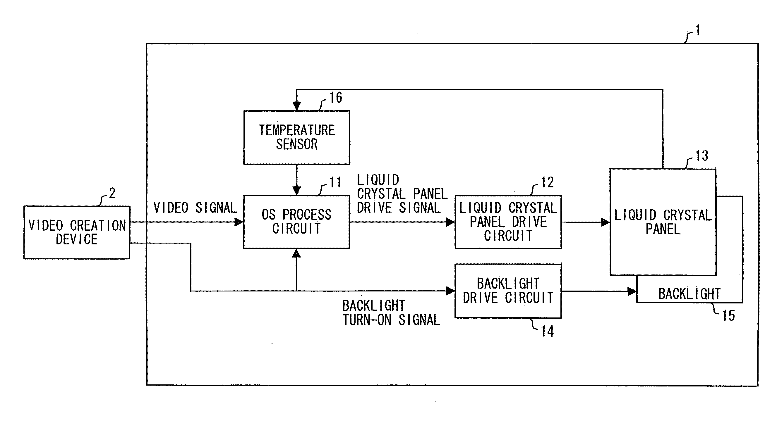
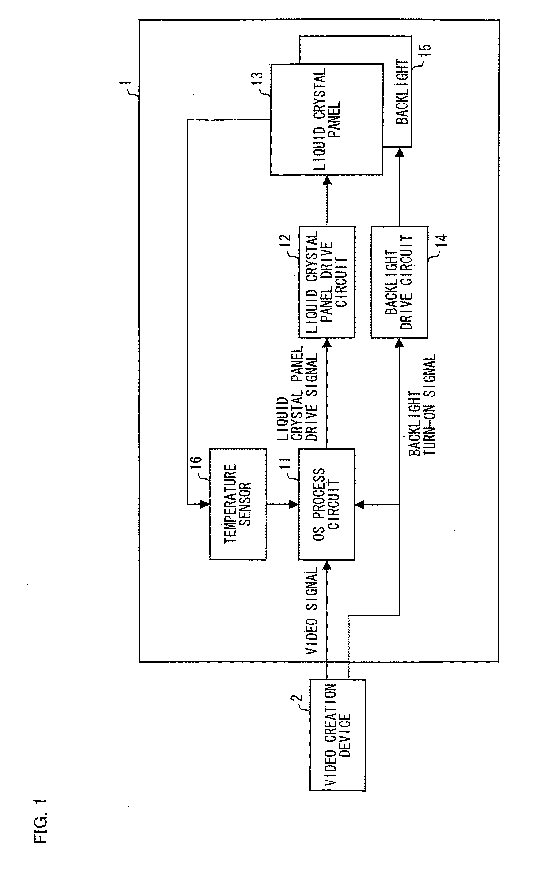
[0062]FIG. 1 is a block diagram schematically showing a configuration of a liquid crystal display system in accordance with the present embodiment.

[0063]The liquid crystal display system shown in FIG. 1 includes a liquid crystal display device 1 and a video creation device 2.

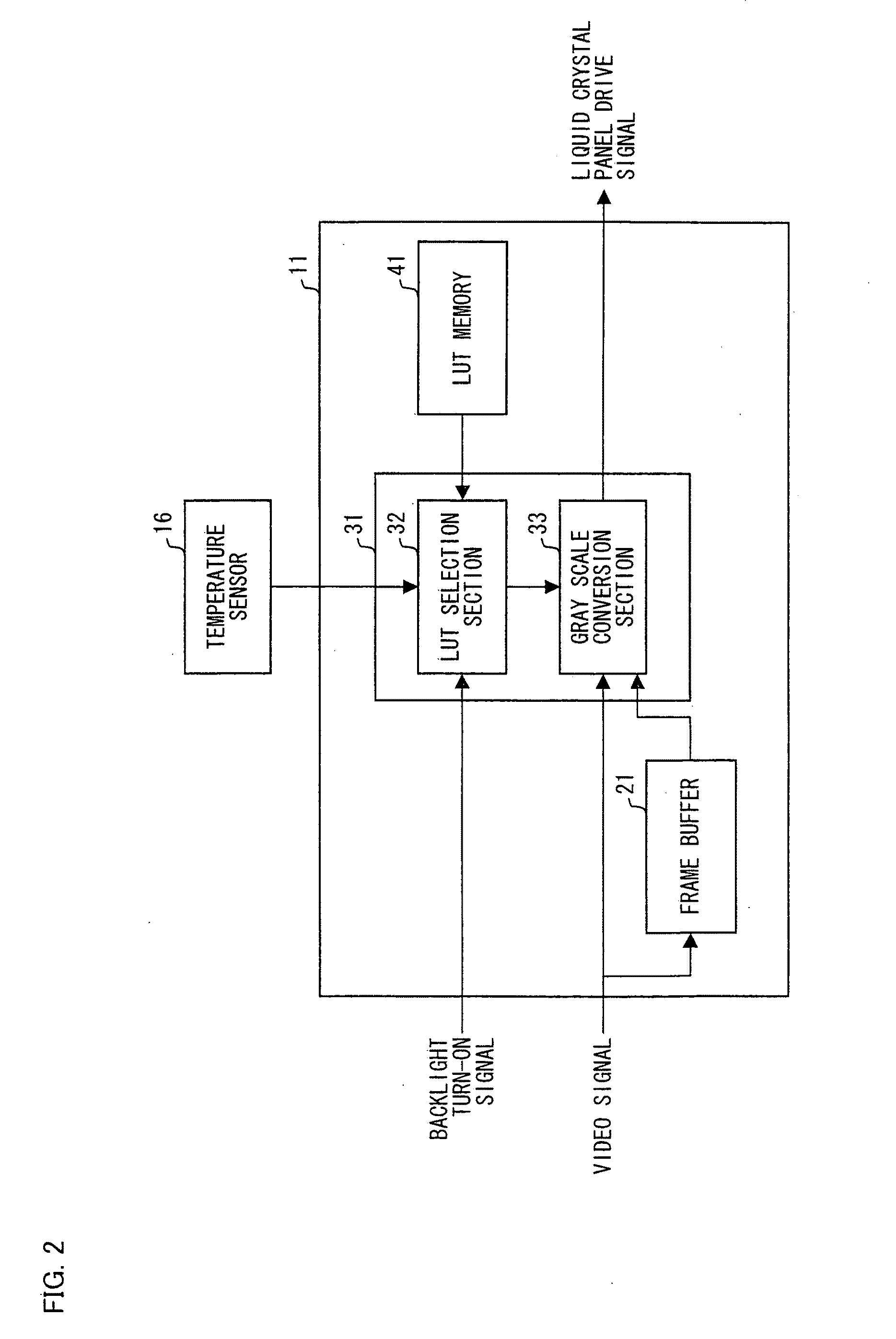
[0064]The liquid crystal display device 1 shown in FIG. 1 includes an overshoot process circuit (hereinafter referred to as “OS process circuit”) 11 for carrying out a gray scale transition emphasis process (hereinafter referred to as “OS drive”) referred to as what is called overshoot drive (overdrive), a liquid crystal panel drive circuit 12, a liquid crystal panel 13, a backlight drive circuit 14, a backlight 15, a temperature sensor 16, and a timing control circuit (TCON) that is not shown in FIG. 1.

[0065]The video creation device 2 supplies, to the liquid crystal display device 1, (i) a video signal (video data signal) and (ii) a...


PUM


Abstract

An object of at least one embodiment of the present invention is to provide a liquid crystal display device and a driving method thereof, in which a contour of an image is clearly recognized during movie display even in a case where a backlight is turned on and off so as to change intervals at which the backlight turns on. In at least one embodiment, the liquid crystal display device includes a liquid crystal panel and the backlight that irradiates the liquid crystal panel with light, one frame period including a turn-on period during which the backlight turns on and a turn-off period during which the backlight turns off, luminance being changed by changing turn-on intervals of the backlight, the turn-on intervals of the backlight being changed by changing lengths of the turn-on period and the turn-off period. The liquid crystal display device further includes an OS process circuit for controlling a drive voltage to be applied to the liquid crystal panel by setting an amplitude of the drive voltage to be applied to the liquid crystal panel during a gray scale transition. The OS process circuit sets the amplitude of the drive voltage to be applied to the liquid crystal panel during the gray scale transition so as to be greater as the turn-on period of the backlight is longer under a condition where gray scales that have not been subjected to a gray scale transition is equal to gray scales that have been subjected to the gray scale transition in a case where the turn-on period of the backlight varies.

Description

TECHNICAL FIELD[0001]The present invention relates to a liquid crystal display device that changes luminance by turning on and off a backlight so as to change intervals at which the backlight turns on, and relates to a method for driving the liquid crystal display device.BACKGROUND ART[0002]Conventionally, there have been known, as display devices, an impulse-type display device such as a CRT (cathode-ray tube) and a hold-type display device such as a liquid crystal display device.[0003]According to the impulse-type display device, pixels in each of which a turn-on period during which an image is displayed on each pixel and a turn-off period during which an image is not displayed on the each pixel are alternated. For example, in a case where a moving image is displayed, a turn-off period is inserted when an image corresponding to one (1) screen is changed. Therefore, a viewer will never recognize any after-image of a moving object. This allows the viewer to clearly distinguish betwe...

Claims


Application Information

Patent Timeline
IPC IPC(8): G09G3/36G09G5/10
CPCG09G3/3426G09G3/3611G09G2310/0237G09G2320/0252G09G2340/16G09G2320/041G09G2320/064G09G2320/0646G09G2330/021G09G2320/0261
Inventor MURAKAMI, HIROFUMITANAKA, YUHJIHORINO, SHINJI
Owner SHARP KK
Why Eureka
Try Eureka