
Signal processing device, signal processing method and program

a signal processing and signal processing technology, applied in signal processing, speech analysis, instruments, etc., can solve the problems of large computational cost in comparison to the separation of source data by ica described above, large computational cost proportional to the number of learning loops, and large computational cost for one learning loop, so as to reduce the computational cost of a learning process in the second separation process, the effect of reducing the computational cos

Inactive Publication Date: 2011-10-27
SONY CORP
View PDF0 Cites 26 Cited by
  • Summary
  • Abstract
  • Description
  • Claims
  • Application Information

AI Technical Summary

Benefits of technology

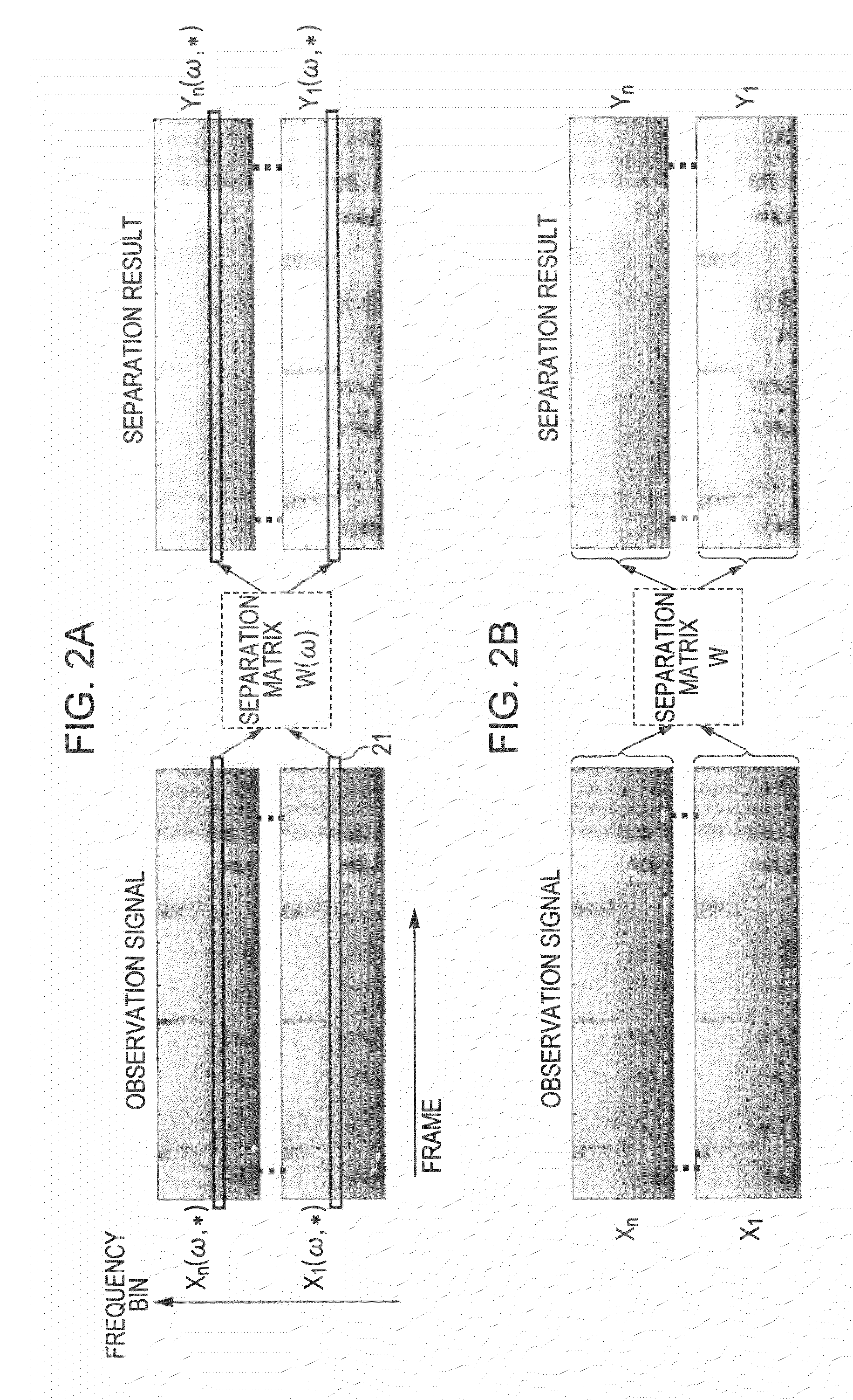
[0073]The present invention takes the above circumstances into consideration, and it is desirable to provide a signal processing device, a signal processing method, and a program that realizes a separation process in which computational cost is reduced in a configuration where a highly accurate separation process is executed in each audio source signal unit by using Independent Component Analysis (ICA).
[0092]According to the configuration of an embodiment of the invention, a device and a method are provided which enables the reduction in computational cost and the higher accuracy in the audio source separation. To be more specific, a separation process of a first stage is executed for the first frequency bins selected from observation signals formed of the mixtures obtained by mixing the output from a plurality of audio sources. For example, first separation results are generated by obtaining separation matrices from a learning process in which ICA is utilized. Furthermore, an envelope representing power modulation in the time direction for channels is obtained based on the first separation results. The second separation results are generated by executing a separation process of the second stage for the second frequency bin data to which a score function in which an envelope is used as a fixed one is applied. Finally, the final separation results are generated by integrating the first separation results and the second separation results. With the process, the computational cost of a learning process in the second separation process can be drastically reduced.

Problems solved by technology

In ICA in the time frequency domain of the related art, a problem, which is called as a permutation problem, occurs that “which component is separated in which channel” is different for each frequency bin.
The audio source separation by ICA describe above has a problem of having large computational cost in comparison to the audio source separation by other method.
(2) Computational cost proportional to the number of learning loops is necessary.
Furthermore, computational cost for one learning loop is also large.
However, ICA using the second-order statistics has a problem in that the separation accuracy is lower than that of ICA using higher-order statistics.
However, the method of being based on the direction of the audio source has a few problems.
For that reason, interpolation is not able to be performed for a sound recorded in an environment with unclear such information.
For the second, another problem is that the direction of the representative audio source obtained in the above Step 2 is not optimum in interpolated frequency bins.
For the third, another problem is that separation accuracy decreases in interpolation when there is unevenness in sensitivity of microphones in the method of generating a separation filter from the direction of an audio source.
In “High-speed Blind Audio Source Separation using Frequency Band Interpolation by Null Beamformer”, for example, a null beamformer (NBF) is used as a method of interpolation, but NBF is not formed with a sufficient blind area when the sensitivity of a microphone is uneven, thereby decreasing separation accuracy as a result.
In other words, there is a trade-off between the computational cost and the separation accuracy.

Method used


Image

  • Signal processing device, signal processing method and program
  • Signal processing device, signal processing method and program
  • Signal processing device, signal processing method and program

Examples


Embodiment Construction

[0110]Hereinbelow, a signal processing device, a signal processing method, and a program will be described in detail with reference to drawings. The description will be provided according to the following subjects.

[0111]1. Overview of a Signal Process of the Present Invention

[0112]2. Specific Embodiment of a Signal Processing Device of the Present Invention

[0113]2-1. Composition of the Signal Processing Device of the Present Invention

[0114]2-2. Process of the Signal Processing Device of the Present Invention

[0115]3. Modified Example of the Signal Processing Device of the Present Invention

[0116]3-1. Modified Example using Another Algorithm in a Signal Separation Process of a Second Stage

[0117](1a) EASI

[0118](1b) Gradient Algorithm with Orthonormality Constraints

[0119](1c) Fixed-Point Algorithm

[0120](1d) Closed Form

[0121]3-2. Modified Example using Other Methods than ICA in the Signal Separation Process of a First Stage

[0122]4. Explanation of Effect by a Signal Process of the Present ...


PUM


Abstract

A signal processing device includes a signal transform unit which generates observation signals in the time frequency domain, and an audio source separation unit which generates an audio source separation result, and the audio source separation unit includes a first-stage separation section which calculates separation matrices for separating mixtures included in the first frequency bin data set by a learning process in which Independent Component Analysis is applied to the first frequency bin data set, and acquires a first separation result for the first frequency bin data set, a second-stage separation section which acquires a second separation result for a second frequency bin data set by using a score function in which an envelope is used as a fixed one, and executing a learning process for calculating separation matrices for separating mixtures, and a synthesis section which generates the final separation results by integrating the first and the second separation results.

Description

BACKGROUND OF THE INVENTION[0001]1. Field of the Invention[0002]The present invention relates to a signal processing device, a signal processing method, and a program. Furthermore, in detail, the invention relates to a signal processing device, a signal processing method, and a program for separating signals resulting from the mixture of a plurality of signals by using Independent Component Analysis (ICA).[0003]Particularly, the present invention relates to a signal processing device, a signal processing method, and a program which enables the reduction of the computational cost by pruning and interpolation of frequency bins in audio source separation using ICA.[0004]2. Description of the Related Art[0005]First of all, as the related art of the present invention, description will be provided on ICA, further on a reduction process of the computational cost by pruning and interpolation of frequency bins, and finally on problems of the related art. So to speak, the description will be ...

Claims


Application Information

Patent Timeline
Patent Type & Authority Applications(United States)
IPC IPC(8): H04B1/00G10L21/028G10L21/0308
CPCG10L21/0272G10L2021/02166H04R3/005H04S2420/07H04S7/30H04S2400/11H04S2400/15H04R2430/03
Inventor HIROE, ATSUO
Owner SONY CORP
Learn More