Fault localization method and a fault localization apparatus in a passive optical network and a passive optical network having the same

a fault localization and fault technology, applied in the direction of transmission monitoring, electromagnetic transmission, testing of fibre optic/optical waveguide devices, etc., can solve the problems of difficult to determine the optical path on which a fault is returned, the economic aspect is not desirable, and the commercially available otdr has a point. achieve high reliability, high reliability and stability, and detect the fault position

Inactive Publication Date: 2011-10-20
KOREA ADVANCED INST OF SCI & TECH
View PDF4 Cites 47 Cited by
  • Summary
  • Abstract
  • Description
  • Claims
  • Application Information

AI Technical Summary

Benefits of technology

[0018]According to the present invention, the following advantages are accomplished:
[0019]1. It is possible to re-configure an optical path of RN through operating electric power of RN temporarily and to detect a fault position of the optical path effectively through a specified subscriber optical path, which is set up, regardless of the type of a subscriber network.
[0020]2. It is possible to have advantages of operating a network with high reliability simultaneously with providing all the advantages of PON having high reliability and stability.

Problems solved by technology

However, there is a difficulty to apply a commercially available OTDR in PON having a Point-to-Multipoint configuration which is comprised of only passive elements from CO to the subscribers.
However, generally such a tunable laser is high-priced and thus using a high-priced OTDR having a high-priced tunable laser is not desirable in the viewpoint of economic aspects.
Further, because a great loss to an OTDR monitoring signal occurs due to a fact that an optical power splitter (OPS) is necessarily to be used in RN and optical signals reflected and returned at respective distribution optical fibers of subscriber channels, i.e., at respective branches, are coupled to a feeder fiber through an OPS in case of TDM-PON, it is difficult to determine a certain optical path that a fault is returned from, even though such a fault is detected.
As a result, a fault detecting method used in TDM-PON makes a whole system complicated, and has low economic efficiency and no compatibility.

Method used


Image

  • Fault localization method and a fault localization apparatus in a passive optical network and a passive optical network having the same
  • Fault localization method and a fault localization apparatus in a passive optical network and a passive optical network having the same
  • Fault localization method and a fault localization apparatus in a passive optical network and a passive optical network having the same

Examples


Embodiment Construction

Technical Problem

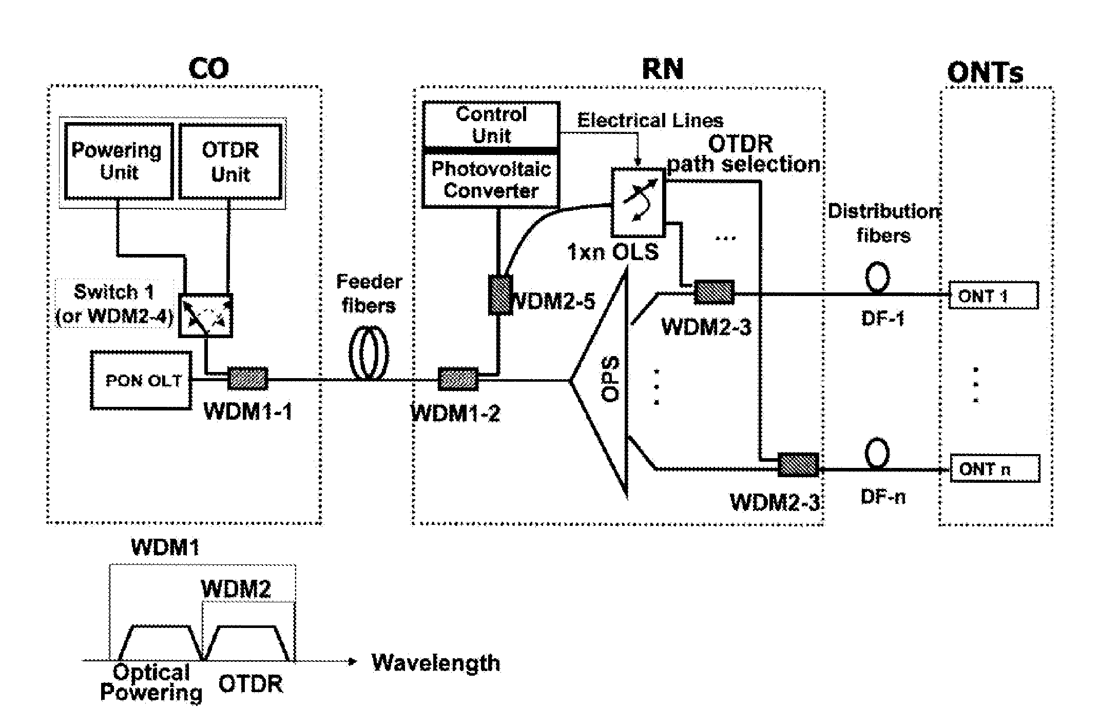
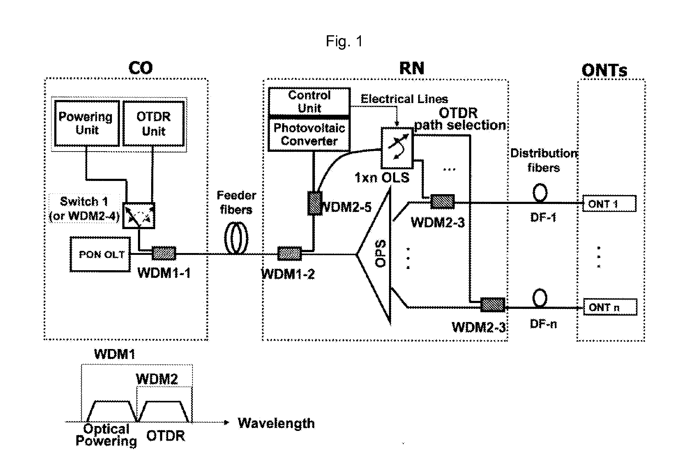
[0008]The object of the present invention is to solve the prior art problems, by providing a fault localization method and a fault localization apparatus and a passive optical network having the fault localization apparatus capable of monitoring a fault of a branched optical path regardless of the type of PON, while using monitoring technology of a known OTDR.

Technical Solution

[0009]According to a first aspect of the present invention, the present invention provides a fault localization method in PON comprising a) configuring an optical path of a remote node (RN) selectively by electric power being fed temporarily only when necessary, while the PON is regularly being operated as a passive network; and b) detecting a fault occurring on the selectively configured optical path by inserting a monitoring signal of an OTDR unit, which is positioned in a central office (CO), through the selectively configured optical path.

[0010]According to a second aspect of the present i...


PUM


Abstract

The present invention discloses a fault localization method and a fault localization apparatus in a Passive Optical Network (PON) and a passive optical network having the same.A fault localization method in PON according to the present invention comprises a) configuring an optical path of a remote node (RN) selectively by electric power being fed temporarily only when necessary, while the PON is regularly being operated as a passive network; and b) detecting a fault occurring on the selectively configured optical path by inserting a monitoring signal of an OTDR unit, which is positioned in a central office (CO), through the selectively configured optical path.

Description

TECHNICAL FIELD[0001]The present invention relates to a fault localization method and a fault localization apparatus in a passive optical network (PON) and a PON having the same. More specifically, the present invention relates to a fault localization method and a fault localization apparatus in a PON and a PON having the same which configure an optical path of a specific distribution fiber selectively though remote control and detects a fault occurring on a feeder fiber or on a specific distribution fiber using a fault detecting device of an optical fiber, a typical example of which is an optical time-domain reflectometer (hereinafter refereed to “OTDR”) through the selectively configured optical path.BACKGROUND ART[0002]It is required to monitor a fault which may occur on PON and to detect and heal rapidly the fault when it occurs in order to enhance reliability of the PON which accommodates demand for sharply increased bandwidth. PON being comprised of only passive elements from ...

Claims


Application Information

Patent Timeline
IPC IPC(8): H04B10/08H04B17/00H04B10/071H04B10/077
CPCG01M11/3136H04B10/0771H04B10/071H04B10/2581
Inventor LEE, CHANG-HEELEE, JONG-HOONCHOI, KI-MANMUN, SIL-GUMOON, JUNG-HYUNGMOON, JUNG-EUNLEE, HOON-KEUNKIM, JOON-YOUNGOH, SANG-MIN
Owner KOREA ADVANCED INST OF SCI & TECH
Why Eureka
Try Eureka