
Data transmitting and receiving method, data transmitting and receiving system, master device, and slave device

a data transmitting and receiving system and data technology, applied in the direction of digital transmission, power distribution line transmission, data switching networks, etc., can solve the problems of transmission failure, transmission data collision, communication failure, etc., to and prevent line utilization efficiency from decreasing

Inactive Publication Date: 2011-09-29
MITSUBISHI ELECTRIC CORP
View PDF7 Cites 11 Cited by
  • Summary
  • Abstract
  • Description
  • Claims
  • Application Information

AI Technical Summary

Benefits of technology

The present invention relates to a data transmitting and receiving method and system in a network system that uses a shared medium for data transmission among multiple communication devices. The invention aims to prevent data collision and ensure stable communication between devices. The invention proposes a method for controlling access to the shared medium by multiple devices through a medium access control (MAC) method. The invention also provides a mechanism for avoiding band assignment requests from multiple devices transmitting at the same time, which can cause data collision and lead to failure in communication. The invention also proposes a new method for improving the utilization efficiency of the shared medium by reducing the collision occurrence frequency of the shared medium.

Problems solved by technology

This is because, when two or more communication devices perform data transmission to the shared medium at the same timing, the transmitted data collide on the transmission path, the data are not separated in the reception devices, and thus communication fails.
Conversely, when the transmission access to the shared medium is extremely restricted, no communication device obtains access right to the shared medium even if there is a communication device having data and desiring the transmission access to the shared medium, and a state of disusing the shared medium continues, which is not preferable from the viewpoint of transmission efficiency.
However, since the band scheduled for the FCH is scheduled for the first time after the band assignment request message is transmitted to the AP, the first band assignment request message cannot be transmitted.
In this case, collision of the transmission data may occur, and the data reception of the AP on the reception side may fail.

Method used


Image

  • Data transmitting and receiving method, data transmitting and receiving system, master device, and slave device
  • Data transmitting and receiving method, data transmitting and receiving system, master device, and slave device
  • Data transmitting and receiving method, data transmitting and receiving system, master device, and slave device

Examples


embodiment 1

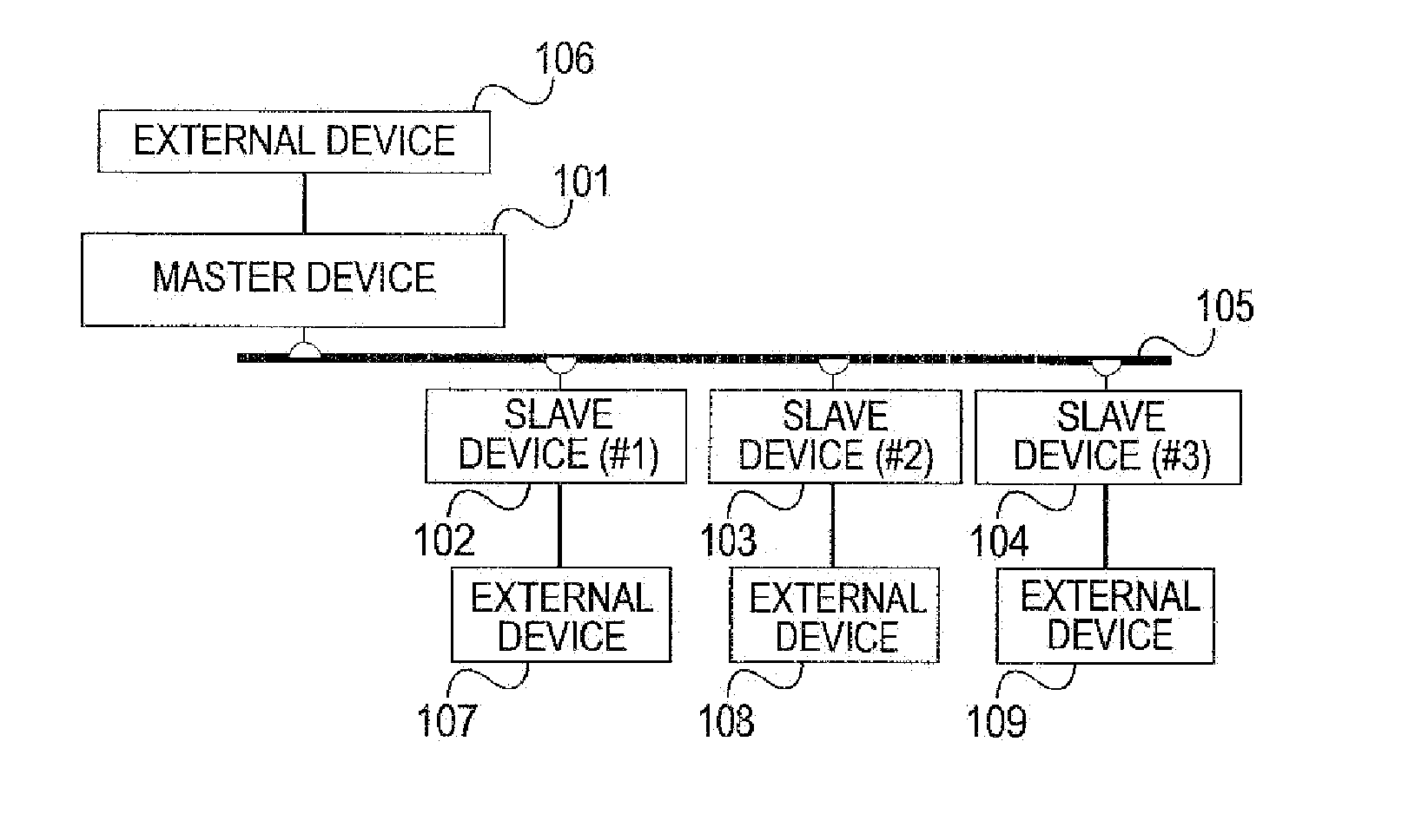
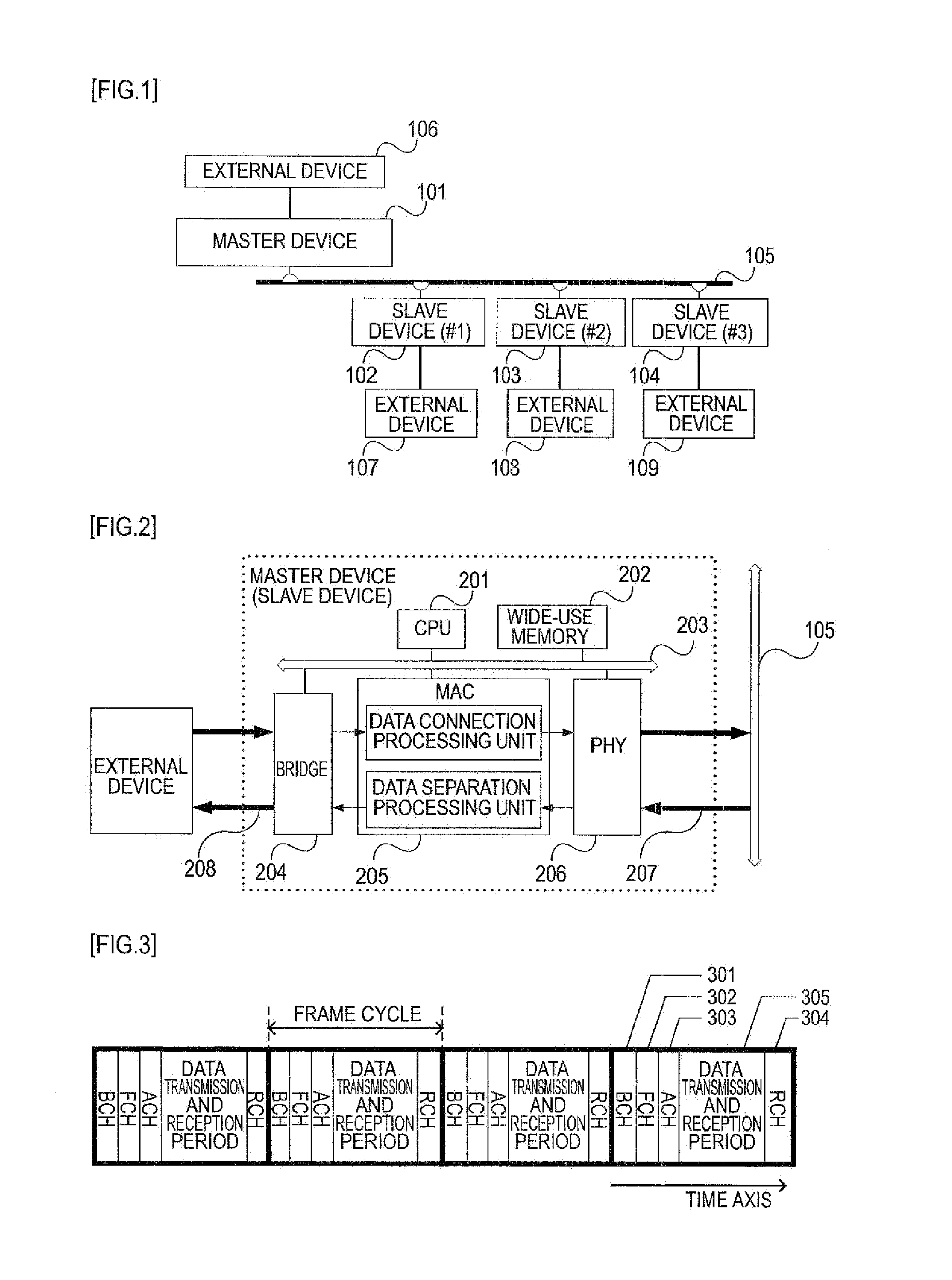
[0032]FIG. 1 is a diagram illustrating an example of a high-speed PLC network system performing data transmission and reception according to Embodiment 1 of the invention.

[0033]In FIG. 1, Reference Numerals 101, 102, 103, and 104 denote PLC modems provided with an I / F for a PLC network, Reference Numeral 101 among these denotes a master device (corresponding to the AP of HiSWANa) managing the entire of the high-speed PLC network, and Reference Numerals 102, 103, and 104 denote slave devices (corresponding to the MT of HiSWANa) connected to the high-speed PLC.

[0034]The devices are connected to a power line 105 which is a common medium by a PLC I / F formed of a power supply outlet, and are connected to external devices such as a PC by an Ethernet (registered trademark) I / F.

[0035]An example of configurations of the master device and the slave devices is shown in FIG. 2. FIG. 2 shows an example of a case where the master device and the slave device have the same configuration.

[0036]In FI...

embodiment 2

[0076]FIG. 9 is a transmission process flowchart in the slave device 102 of the embodiment, and a basic device and a system configuration are the same as those of Embodiment 1.

[0077]The slave device in Embodiment 2 may be subjected to the assignment of the polling band in the same manner as Embodiment 1. Accordingly, when the user data to be transmitted is kept, the schedule information is acquired from the FCH 302, and it is determined whether or not there is the polling band assignment of the slave device (ST901). When there is no polling band assignment, the polling band assignment after the next frame cycle is awaited in the same manner as Embodiment 1 and the transmission and reception process in the frame cycle is ended.

[0078]When the assignment of the polling band is detected by the FCH 302, the assignment band size is further acquired from the schedule information in the polling band (ST902), and a data length which can be transmitted in the assignment band size is calculate...

embodiment 3

[0082]FIG. 10 shows a specific schedule process flow of the embodiment. In the embodiment, a basic device and a system configuration are the same as those of Embodiment 1, and thus the description thereof is omitted. As for the process flow, the same number is given to the same process as that of FIG. 8, and the description thereof is omitted.

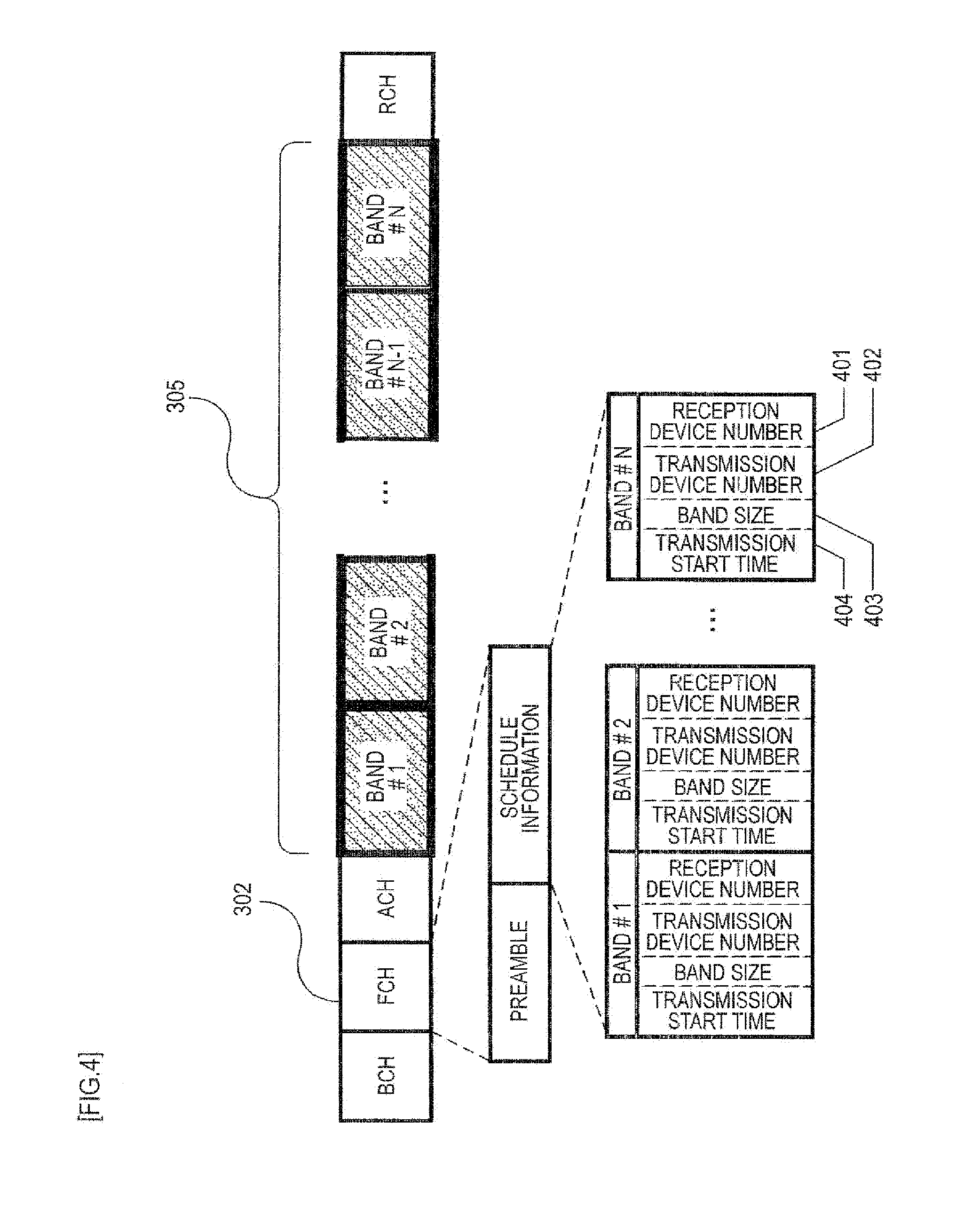
[0083]The master device in Embodiment 3 performs the assignment of the polling band with respect to the number of devices designated by the polling assignment number from the slave device introduced to the network in the same manner as Embodiment 1, and further schedules the assignment of the band requested for assignment from the slave device.

[0084]The completion of the assignment of the band requested for assignment from the slave device is the same when the assignment request is never received from the slave device (ST702: No), when the assignable remaining size is shorter than that of the assignment of a new band assignment request (ST704: ...


PUM


Abstract

In a data transmitting and receiving method of a demand assignment type, a master device schedules an occupancy band of a fixed size for requesting a band to the master device by slave devices, with respect to a specific number of slave devices for each cycle, and the slave device waits for assignment of the occupancy band of the fixed size based on the schedule and performs message transmission of requesting a band for data transmission to the master device, thereby suppressing an influence of pressure on the data transmission band and preventing line utilization efficiency from decreasing while avoiding signal collision on a Random Channel.

Description

TECHNICAL FIELD [0001]The present invention relates to a data transmitting and receiving method, a data transmitting and receiving system, a master device, and a slave device in a network system in which a plurality of communication devices perform data transmission sharing the same medium such as high-speed PLC (Power Line Communication) and wireless LAN.BACKGROUND ART [0002]When a plurality of communication devices performs data transmission sharing the same medium such as wireless or high-speed PLC, it is necessary to perform control such that two or more communication devices do not perform data transmission to the same medium at the same timing. This is because, when two or more communication devices perform data transmission to the shared medium at the same timing, the transmitted data collide on the transmission path, the data are not separated in the reception devices, and thus communication fails.[0003]Conversely, when the transmission access to the shared medium is extreme...

Claims


Application Information

Patent Timeline
Patent Type & Authority Applications(United States)
IPC IPC(8): G06F15/16
CPCH04B3/54H04L12/4035H04B2203/5408H04L5/0091H04L12/413H04L47/13
Inventor MAEDA, YASUO
Owner MITSUBISHI ELECTRIC CORP
Learn More