
Battery charger for charging batteries of different sizes

a battery charger and charger technology, applied in the field of battery chargers, can solve the problems of enlarge the size of the charger and consequently its cost, lack of flexibility to accommodate different sized electronic components within a single compact docking mechanism, and unsatisfactory user experience, etc., and achieve the effect of flexible charging of different sized components

Inactive Publication Date: 2011-09-29
EASTMAN KODAK CO
View PDF8 Cites 20 Cited by
  • Summary
  • Abstract
  • Description
  • Claims
  • Application Information

AI Technical Summary

Benefits of technology

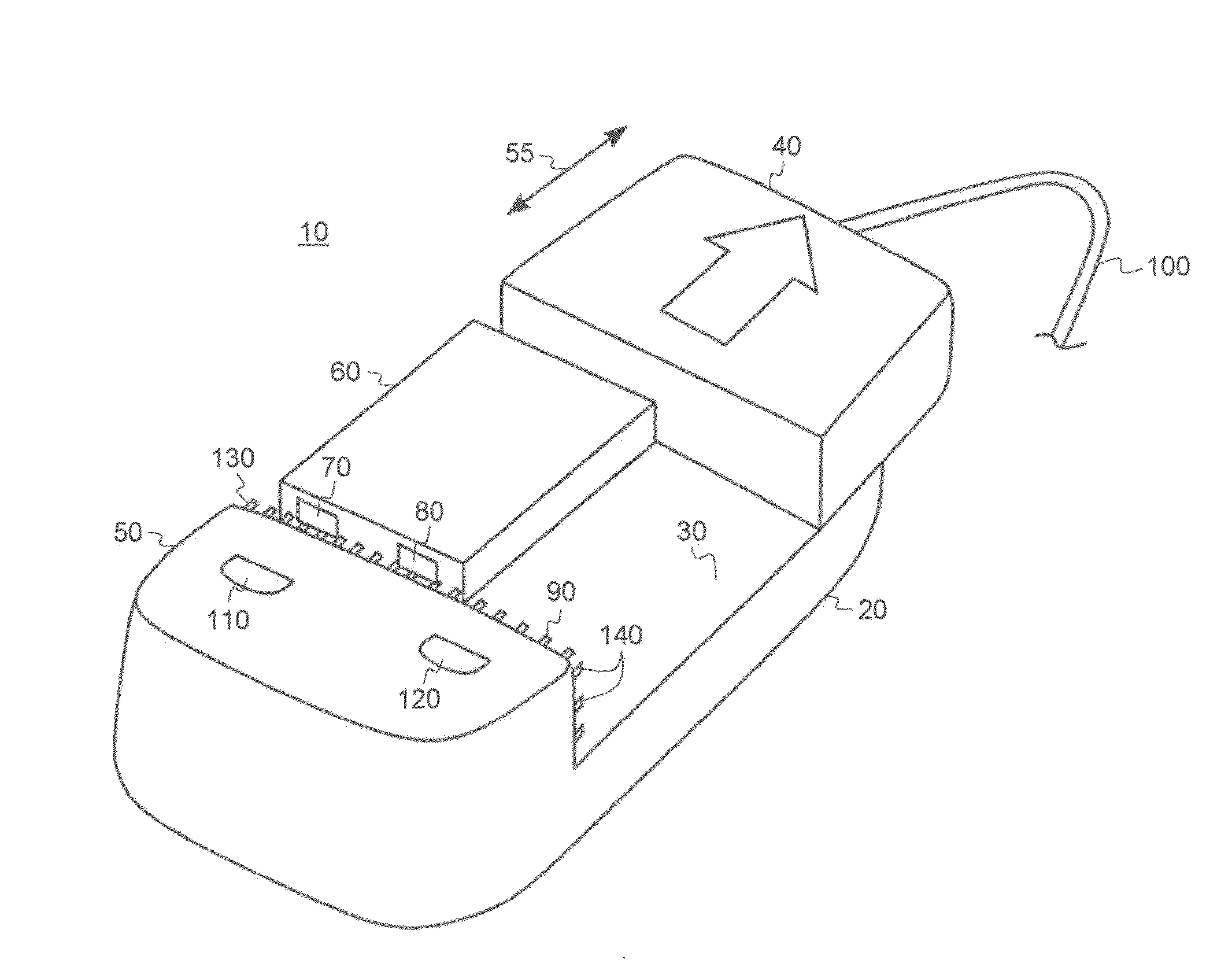
The present invention is a battery charger that can charge batteries of different sizes. It has a charging platform with movable ends that can adjust the area where the battery rests. The charger has a matrix of pogo pins that make contact with the battery in multiple positions within a certain range. It also has electronic components to detect the polarity of the battery. The charging is done based on the detected polarity. The technical effect of this invention is to provide a charger that can accommodate batteries of different sizes and ensure proper charging based on the detected polarity.

Problems solved by technology

(See page 14) Although satisfactory for the scope of testing envisioned by this application, it lacks flexibility to accommodate different sized electronic components within a single compact docking mechanism.
Although satisfactory for the scope of testing envisioned, the separate supports enlarge the size of the charger and consequently its cost.
Still further, the lock out feature is inflexible in its ability to charge batteries if the proper battery is not installed in the correct support, which makes the user have to obtain and retain its operation characteristics in order to efficiently operate.
This is obviously not particular user friendly.
(See column 7, lines 12-30) Likewise, this disclosure is satisfactory for the anticipated scope of charging, but is obviously limited to its envisioned testing parameters such as unique docking trays and limited detection.
(See column 2, lines 26-34) This imposes additional cost and greatly increases its size.
Although satisfactory for its envisioned scope, the retractable walls include mechanical devices beneath the floor that are costly and also create mechanical reliability issues due to its complexity.

Method used


Image

  • Battery charger for charging batteries of different sizes
  • Battery charger for charging batteries of different sizes
  • Battery charger for charging batteries of different sizes

Examples


Embodiment Construction

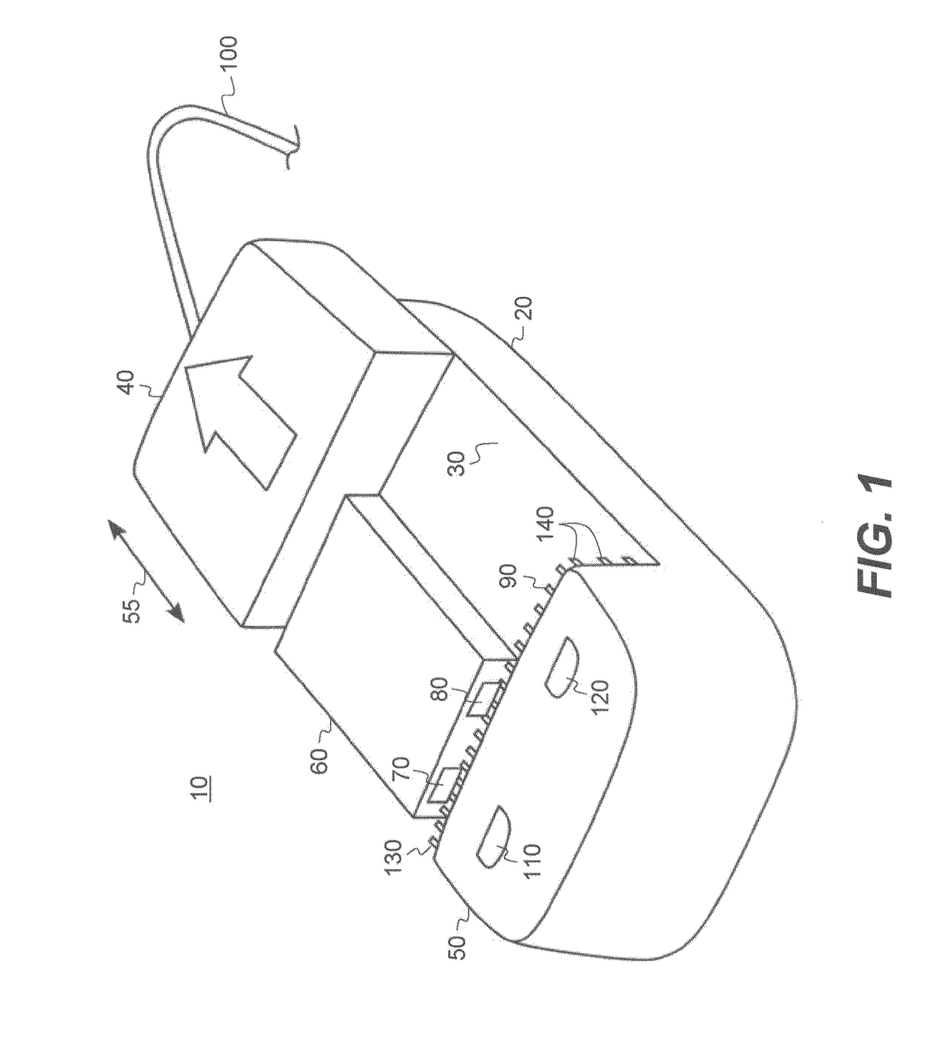
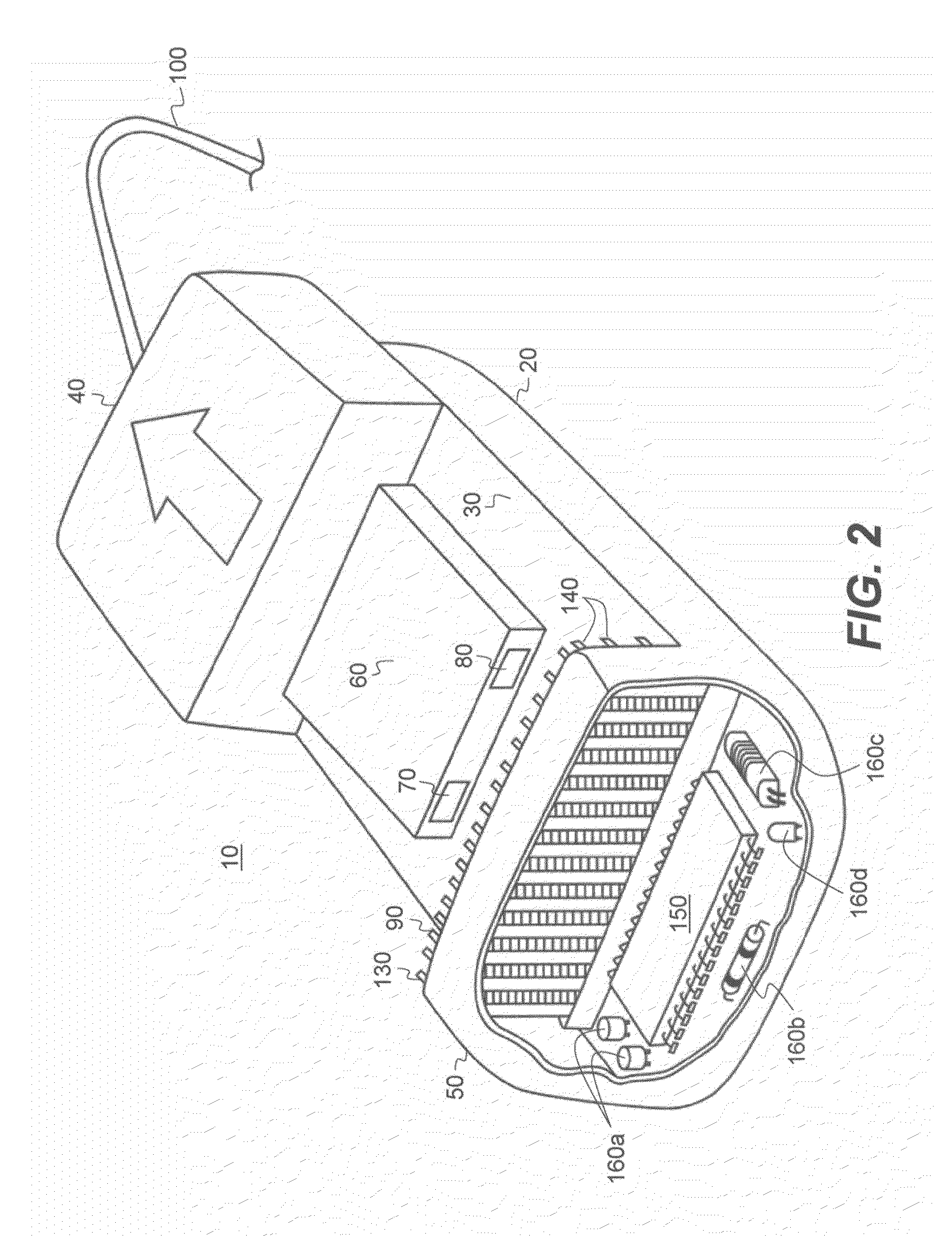
[0015]Turning now to FIG. 1, there is shown a perspective view of a battery charger 10 of the present invention. The battery charger 10 includes a housing 20 having a charging platform 30 (a single, undivided unit) with two closed ends 40 and 50 respectively on each end of the platform 30. A battery 60, when being charged, rests on the platform between the two closed ends 40 and 50. It is noted that the battery 60 includes two terminals 70 and80 on a side of the battery, as is typical, that are used for charging the battery 60. One end 50 includes a matrix of pogo pins 90 in which the pins 90 move toward the closed end 50 when force is applied and returns to it normal position (as shown) when there is an absence of force.

[0016]The other end 40 (i.e., a movable, self-adjusting end) is adjustable inwardly toward the pogo pin end 50 and outwardly away from the pogo pin end 50 (as indicated by the arrows 55) for adjusting to the size of the particular battery being charged. The adjustab...


PUM


Abstract

Battery charger for charging batteries of different sizes in which the batteries have first and second terminals on one side of the battery, the battery charger includes a charging platform for receiving a battery; first and second closed ends disposed on opposite ends of the charging platform; wherein one of the closed ends is movable in first and second directions that span across at least a portion of the platform for respecting increasing and decreasing an area of the platform in which the battery rests for receiving batteries of different sizes; a matrix of pogo pins disposed on one of the closed ends of the platform, wherein the pogo pins are configured to electrically contact the battery in a plurality of positions within a predetermined range; and one or more electronic components for detecting polarity of the battery; wherein charging of the battery is performed according to the detected polarity.

Description

FIELD OF THE INVENTION[0001]The present invention generally relates to battery chargers and more particularly to battery chargers having a single, adjustable docketing station for accommodating batteries of different sizes and a detection mechanism for detecting the polarity of the battery and then charging accordingly.BACKGROUND OF THE INVENTION[0002]Current electronic testing devices include pogo pins that contact terminals of the device being tested. For example, PCT Application WO 2007 / 013341 A1 includes a base having multiple pogo pins that “prevent damage to the electrode pads of the electronic component device and the first contacts when they are brought into contact with each other.” (See page 11) The PCT Application also discloses that, if different sized electronic components are tested, then another set of pogo pins are required. This limits this disclosure to having a set of pogo pins for each anticipated battery size. If the beforehand determination of the number of pog...

Claims


Application Information

Patent Timeline
Patent Type & Authority Applications(United States)
IPC IPC(8): H02J7/00
CPCH02J7/0009H02J7/00043H02J7/00047
Inventor SMITH, STEPHEN J.
Owner EASTMAN KODAK CO
Learn More