
Optimized Multistatic Surveillance System

a multi-static surveillance and monitoring system technology, applied in the field of radar surveillance, can solve the problems of insufficient resolution requirements for detection systems, inability to meet the resolution requirements of detection systems, and installation comprising communication means using wire links, and by its nature, will be less easy to deploy over a wide monitoring area

Active Publication Date: 2011-09-08
THALES SA
View PDF23 Cites 7 Cited by
  • Summary
  • Abstract
  • Description
  • Claims
  • Application Information

AI Technical Summary

Benefits of technology

The invention provides an optimized solution for producing a multistatic radar detection system that meets various requirements. The system includes a command and control unit that controls the configuration of multiple transmitter elements and receiver elements via command links and processes the detection information produced by the receiver elements. Each transmitter element transmits a signal modulated according to a binary code specific to it, while each receiver element decodes the received signals and identifies the transmitter that is the source of the signal. The coding applied to the waveform ensures that the spread spectrum caused to the signal transmitted by a given transmitter does not exceed the frequency band allocated to the system. The command and control unit can also transmit and receive messages relating to the operating state of the elements, their geographic position, and the detection of objects in the space covered by the receiver. The technical effects of the invention include improved radar detection and improved communication between the elements of the system.

Problems solved by technology

Consequently, when such a system is used, various problems arise, amongst which it is possible to cite:
problems associated with the spectrum of the transmitted signals and with the determination of the source of the received signals,
problems associated with using communication means between the various elements of the system and the command unit,
problems associated with the tolerance of the system to faults,
problems associated with the capacity of the system to adapt to variations in its environment.
The problems associated with the spectrum of the signals transmitted and to the determination of the source of the signals received originate notably from the fact that a given receiver can exploit the signals that it receives only if it can identify and locate the source that has transmitted the radioelectric signal in question.
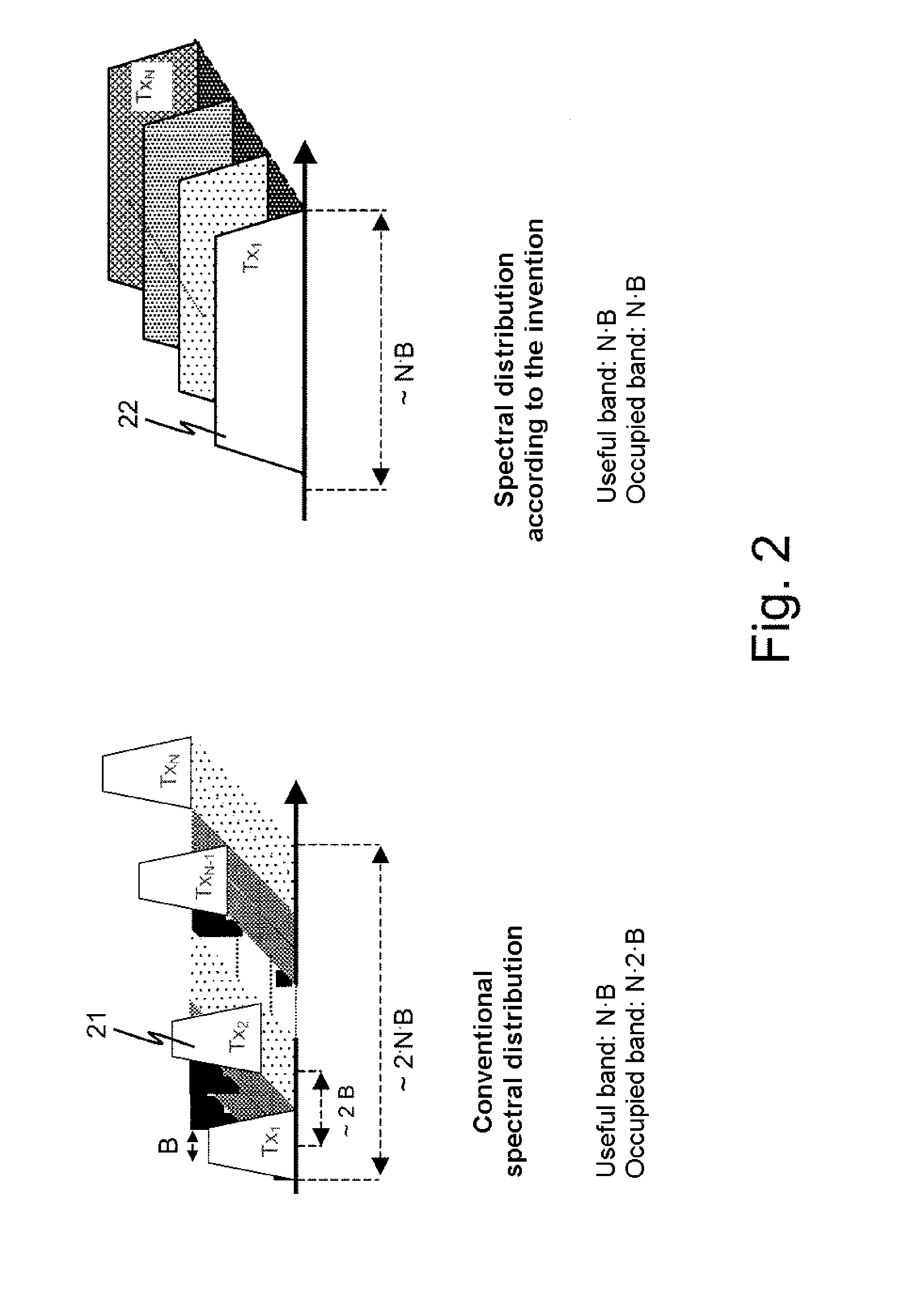
However, if the system uses a considerable number of transmitters, each transmitter has a limited bandwidth for transmitting which, because the total frequency band allocated to the system is necessarily limited, may be insufficient to satisfy the resolution requirements imposed on the detection system.
The problems associated with using communication means between the various elements of the system and the command unit are, for their part, usually associated with the compromise to be made between the cost of producing and using the chosen means and the requirement to produce a multistatic detection system having a given flexibility.
On the other hand, an installation comprising communication means using wire links will, by its nature, be less easy to deploy over a wide monitoring area.
It will also be more likely to see its effectiveness degraded, and even to break down, because of the intentional or unintentional breakdown of one or more wire links, which breakdown may occur during the period of operation of the system.
Moreover, a wire communication structure seems in practice to be not very well suited to the deployment of a mobile detection system.
The problems associated with the capacity of the system to adapt to variations in its environment relate in particular to the capacity of the detection system to modify the waveforms transmitted by the various transmission means according to variations of the environment in which the surveillance zone is situated.
This capacity is in practice limited by the bandwidth allocated to each transmitter, so that this capacity to adapt is usually limited.
Consequently the addition of means materializing these solutions makes the use of the system more complex and the system itself more costly.

Method used


Image

  • Optimized Multistatic Surveillance System
  • Optimized Multistatic Surveillance System
  • Optimized Multistatic Surveillance System

Examples


Embodiment Construction

[0032]The issue here is the problem of primary surveillance, that is to say surveillance not requiring cooperation on the part of the objects that it is sought to detect, these objects being able to be land, naval, air or space objects.

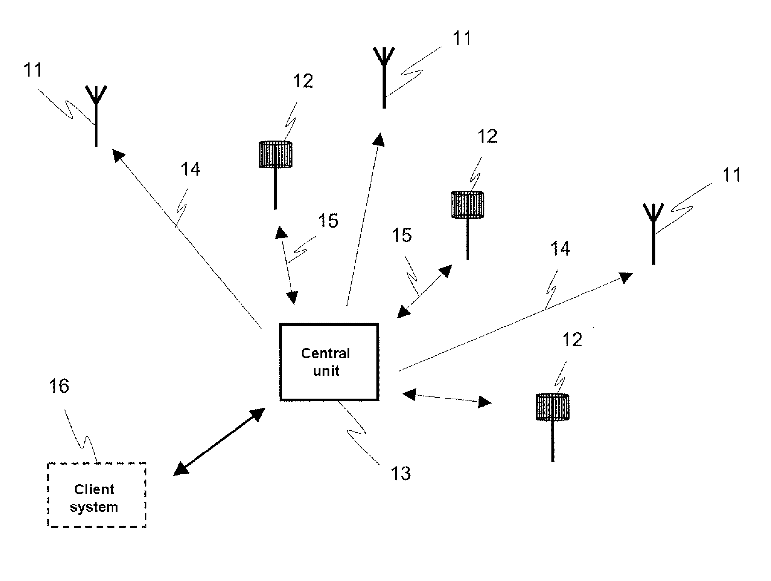
[0033]As illustrated in FIG. 1, the solution provided by the architecture according to the invention is based on the use of a network of omnidirectional transmitters 11 and receivers 12, the transmitters and the receivers being configured so as to be linked with one another and with a command and control unit 13 which may itself consist of various elements spread out or located in one and the same location as illustrated in FIG. 1. This command and control unit mainly configures the various elements of the system, transmitters and receivers and uses the information produced by the receivers, the information produced by a receiver relating mainly to the features of the objects detected by this receiver.

[0034]If necessary, the information produced may a...


PUM


Abstract

A multistatic radar surveillance system includes transmitter elements and receiver elements arranged according to a zone to be monitored, and a command and control unit that configures the elements and collects information relating to objects detected by the receiver elements. Each transmitter element transmits a signal, the bandwidth of which is substantially equal to the totality of a frequency band B allocated to the system. Each transmitter element transmits a common waveform to all of the transmitter elements, and the waveform is modulated by a binary signal specific to the element in question, this signal allowing each of the receiver elements receiving a signal to identify the transmitter element at the source of this signal. The coding applied to the waveform is defined so that the spread spectrum caused to the signal transmitted by the latter does not exceed the frequency band B allocated to the system.

Description

CROSS-REFERENCE TO RELATED APPLICATIONS[0001]This application is a continuation of pending U.S. application Ser. No. 12 / 781,161, filed on May 17, 2010, which claims priority to foreign French patent application No. 09 02365, filed on May 15, 2009, the disclosures of which are herein incorporated by reference in their entireties.FIELD OF THE INVENTION[0002]The invention relates to the field of radar surveillance, and in particular the field of surveillance systems using multistatic equipment (transmitters, receivers and central units) which are fixed or carried by mobile platforms (land, naval, air or space vehicles).BACKGROUND OF THE INVENTION[0003]Multistatic surveillance systems, in a known manner, have certain specific features which differentiate them in terms of design, production, deployment and maintenance from monostatic systems.[0004]Amongst these specific features it is possible in particular to note the fact that such a system usually uses the radioelectric transmissions ...

Claims


Application Information

Patent Timeline
Patent Type & Authority Applications(United States)
IPC IPC(8): G01S13/04
CPCG01S7/003G01S13/878G01S13/288G01S13/003
Inventor MORUZZIS, MICHELMULLER, DANIELFERRIER, JEAN-MARIE
Owner THALES SA
Learn More