
System and method for location of mobile devices in confined environments

a mobile device and confined environment technology, applied in the field of wireless transceiver systems, can solve the problems of difficult accurate positioning of the mobile device used to place the call, limited or insufficient direct rf penetration from the base station, and especially challenging

Active Publication Date: 2011-09-01
COMMSCOPE TECH LLC
View PDF59 Cites 206 Cited by
  • Summary
  • Abstract
  • Description
  • Claims
  • Application Information

AI Technical Summary

Benefits of technology

The invention is a sensor network that includes multiple sensors with a controller and RF receiver for receiving RF signals. The sensors also have a global positioning receiver for receiving signals from a global positioning system and a localization engine for receiving beacon signals from other sensors in the network. The controller of each sensor uses the RF receiver, global positioning receiver, and localization engine to determine its position. The sensors communicate their position to a location capture processing unit. This allows for accurate positioning of the sensors in the network. Additionally, the invention provides a distributed antenna system with integrated sensors and coverage antennas for improved location tracking.

Problems solved by technology

One of the issues with only having a mobile phone is related to emergency phone calls such as 911 in the Unites States and Canada or 112 in the European Union and the difficulty in accurately locating the mobile device used to place the call.
This can be especially challenging if the call originated in a multistory building.
However, repeaters and distributed antenna systems (DAS) further extend coverage into areas where the direct RF penetration from base stations is limited or insufficient.
However, contemporary RF and GPS solutions used in outdoor environments are insufficient to provide the needed location data for some of the extended coverage areas, especially inside buildings and other confined spaces.

Method used


Image

  • System and method for location of mobile devices in confined environments
  • System and method for location of mobile devices in confined environments
  • System and method for location of mobile devices in confined environments

Examples


Embodiment Construction

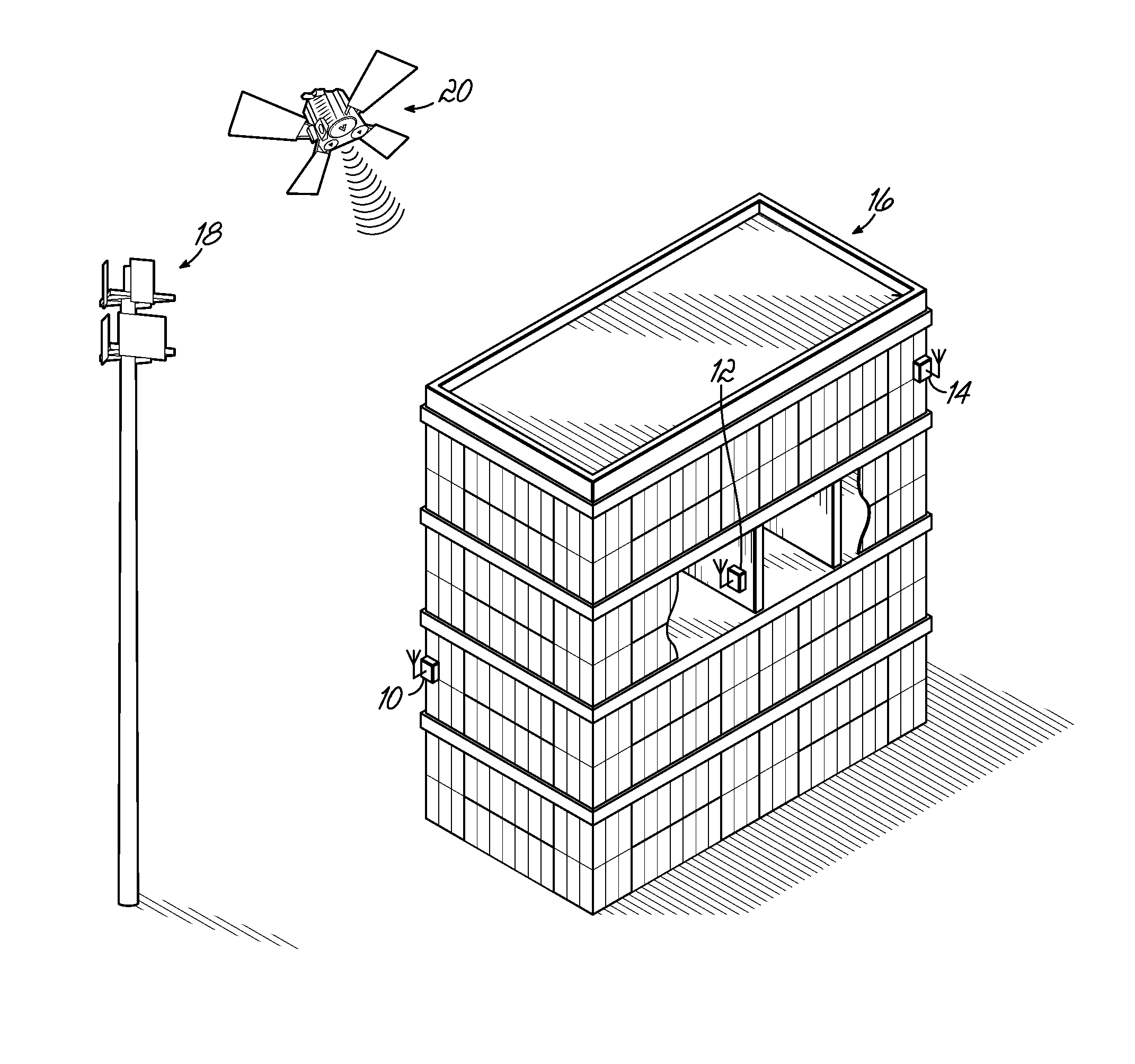
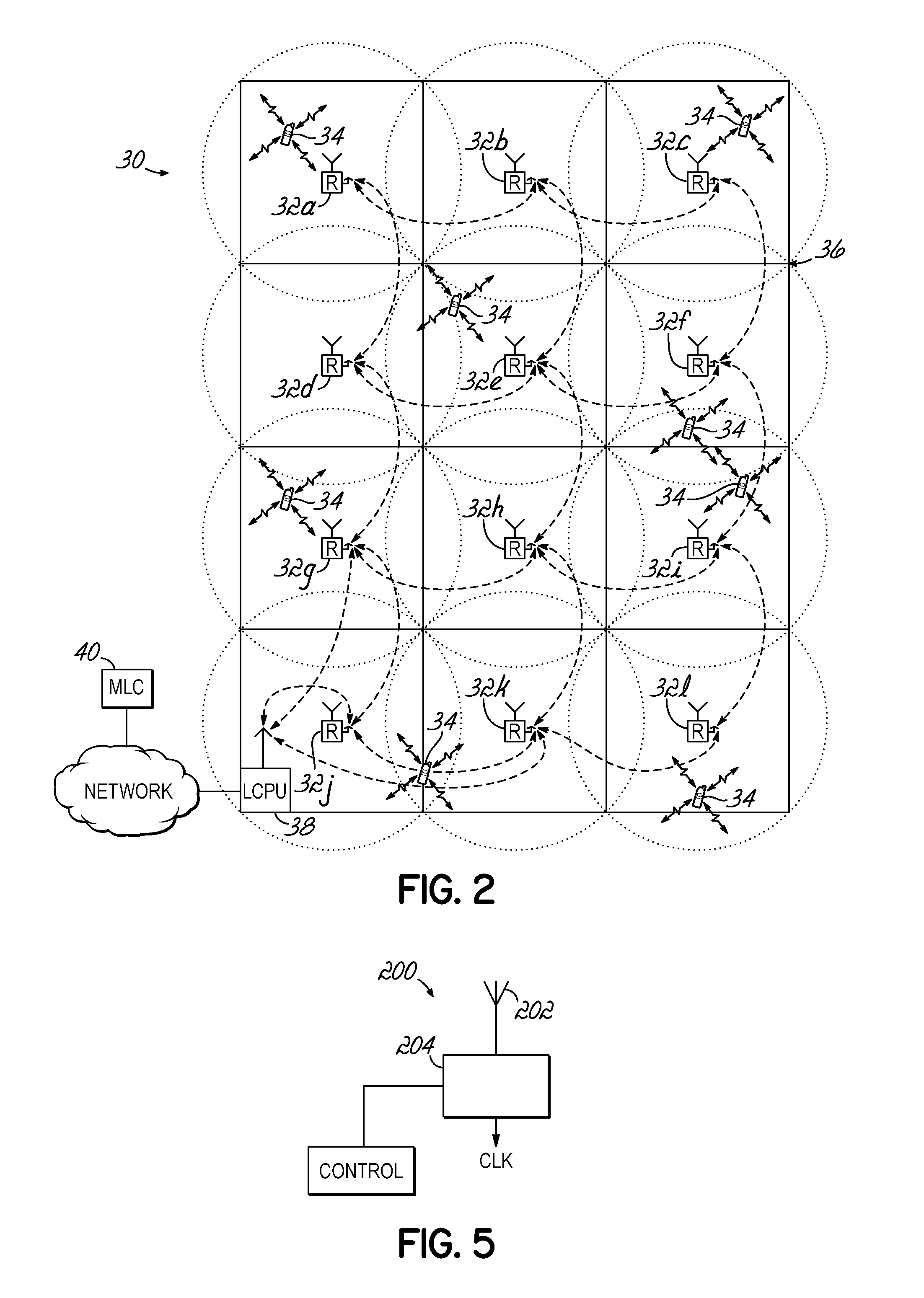
[0022]Existing outdoor solutions for the location of mobile devices cannot easily be used with the same accuracy in indoor or other confined areas and spaces. As illustrated in FIG. 1, location 10, 12, and 14 may be placed in and around a building 16 to expand the ability to locate a mobile device from base station 18. The location of the sensors 10 and 14 located either outside the building 16 or inside near a window may determine their location based on RF transmissions with a plurality of local base stations, such as the base station 18 (or a repeater) for example. Alternatively, the locations of location sensors 10 and 14 may be determined from GPS 20 signals. However, the location of sensor 12 may not be readily known as the RF signals from the base station 18 and / or signals from a GPS 20 may be blocked or shielded by building 16, inhibiting a direct path for providing location information even if the location of sensor 12 was known relative to the building 16. Furthermore, eve...


PUM


Abstract

The sensor network may include a location capture processing unit; and a plurality of sensors in communication with the location capture processing unit. Each sensor of the plurality of sensors includes a controller and a RF receiver configured to receive RF signals. The RF receiver is in communication with the controller. A localization engine is configured to receive beacon signals transmitted by other sensors in the sensor network. The localization engine is in communication with the controller. The controller of each of the plurality of sensors is further configured to determine a position of its respective sensor using either RF receiver or localization engine or both. The plurality of sensors communicates their position to the location capture processing unit.

Description

FIELD OF THE INVENTION[0001]The present invention is directed to wireless transceiver systems for use in wireless communications, and specifically is directed to determining locations of mobile wireless devices.BACKGROUND OF THE INVENTION[0002]The use of wireless communication devices such as wireless telephones, pagers, personal digital assistants, laptop computers, etc. has become prevalent in today's society. In some instances individuals have forgone the traditional POTS service and rely totally on their wireless mobile devices. One of the issues with only having a mobile phone is related to emergency phone calls such as 911 in the Unites States and Canada or 112 in the European Union and the difficulty in accurately locating the mobile device used to place the call. This can be especially challenging if the call originated in a multistory building.[0003]Recently, at the urging of public safety groups, there has been increased interest in technology which can determine the geogr...

Claims


Application Information

Patent Timeline
Patent Type & Authority Applications(United States)
IPC IPC(8): G08B23/00G08B5/22G08B17/00G08B17/10
CPCG01S5/0289G01S5/06H04W24/00G01S19/48
Inventor KUMMETZ, THOMAS
Owner COMMSCOPE TECH LLC
Learn More