[0004]It is an object of the invention to provide a centrifuge which, when installed for example on an
internal combustion engine, allows the centrifuging drum to be emptied without the need to perform
assembly work on the centrifuge housing.
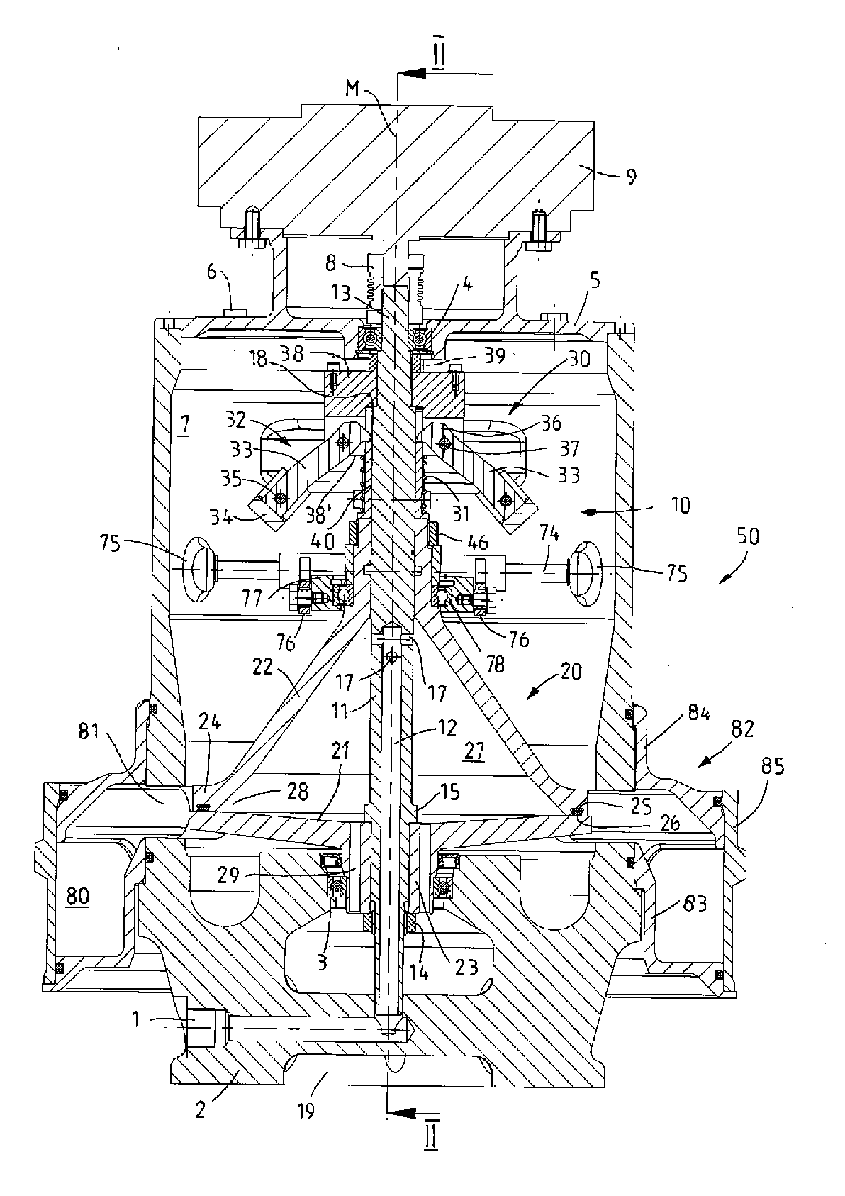
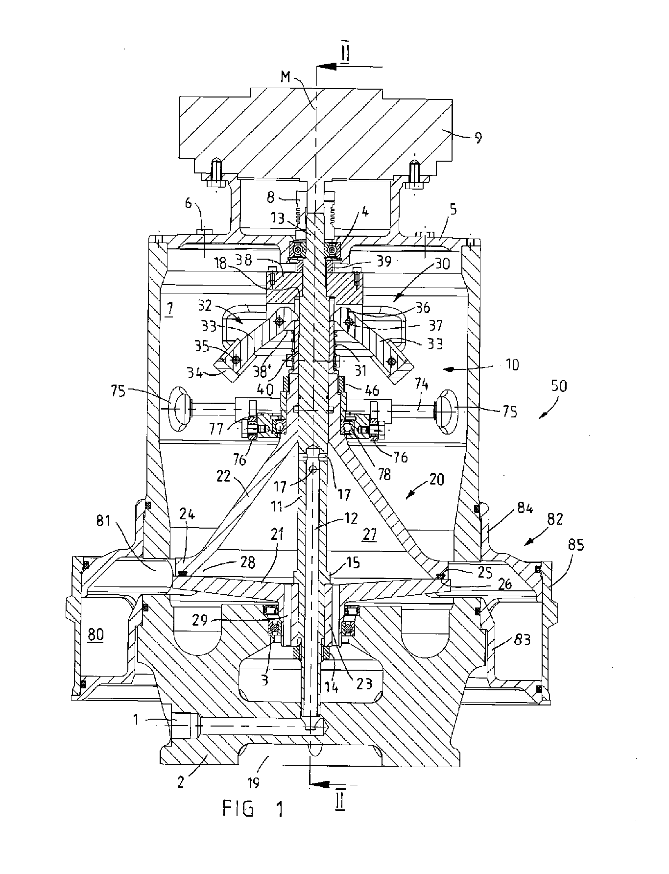
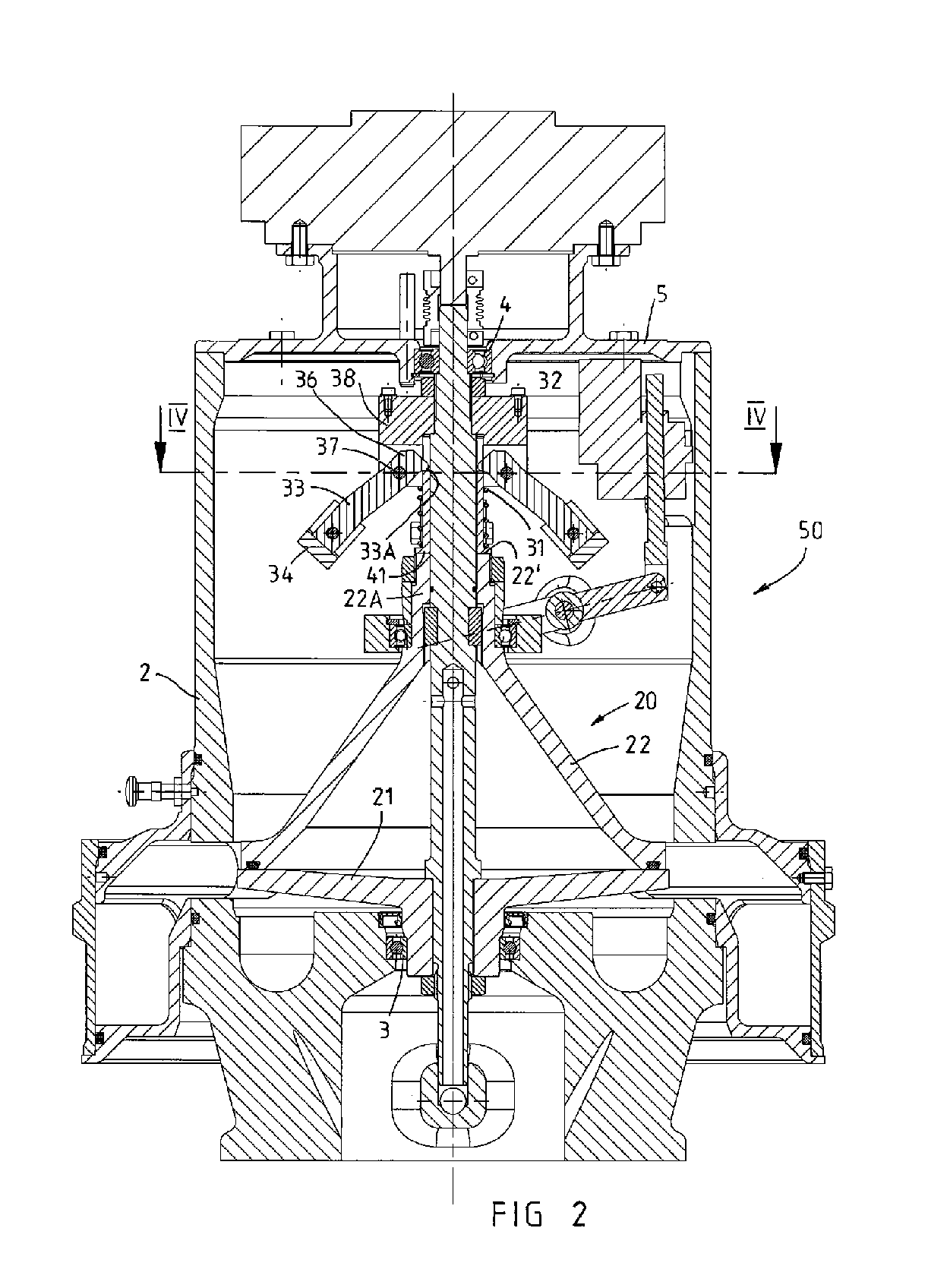
[0006]In a preferred embodiment, the disengagement mechanism is connected to a bearing ring on which the drum upper part is rotatably mounted by means of a rotary bearing. In this way, it is possible for the drum upper part of the centrifuging drum to be rotated in a relatively simple manner even when the drum lower part and drum upper part are spaced apart from one another by means of the disengagement mechanism, since the rotary bearing in the bearing ring can serve at least to rotatably support the raised drum upper part, and the bearing ring itself may remain positionally fixed and thus interact with a stationary disengagement mechanism. In the particularly preferred refinement, the disengagement mechanism has a disengagement arm which is mounted in a tiltable fashion on the centrifuge housing and whose one arm section is coupled to the bearing ring and whose other arm section is coupled to an actuating mechanism. As an actuating mechanism, it is possible in particular to use a suitable actuating drive, for example an electric spindle drive or magnetic lifting drive, in order to induce a movement of the one end of the disengagement arm by actuating the actuating drive, which disengagement arm, on account of a centrally or eccentrically arranged tilting bearing, generates an opposing movement of the other disengagement arm which generates a lifting movement for the bearing ring and, via the latter, also of the drum upper part. It is particularly advantageous if the bearing ring is coupled to the arm section with axial play since, in the closed position of the centrifuging drum in which the drum lower part and drum upper part bear against one another, the rotary bearing in the bearing ring, relieved of the load of the weight forces of the centrifuging drum, may then co-rotate with its drum-side bearing shell and is loaded with the weight forces of the centrifuging drum substantially only when the drum lower part and drum upper part are spaced apart from one another by means of the disengagement mechanism, and are consequently situated in an emptying position.
[0008]It is particularly advantageous both with regard to the centrifuge and also with regard to a centrifuge rotor if a seal, in particular an O-ring, is arranged on an edge web of the drum upper part, which edge web is of cylindrical or preferably funnel-shaped design, in order to seal off the interior space when the centrifuging drum is closed. The drum lower part may preferably be of plate-shaped or disc-shaped design in order that, in the
closed state, an edge web of the drum upper part bears against the upper side of the drum lower part with the interposition of, and so as to clamp, the seal, and the sealing function of the seal between the drum lower part and drum upper part can be ensured. In the particularly preferred refinement, to obtain reliable sealing of the interior space even at high rotational speeds of for example more than 5000 rpm which may be introduced into the rotor shaft of the centrifugal rotor by means of the external motor, a pressure-exerting mechanism for increasing the pressure forces between the drum upper part and drum lower part in the
closed state of the centrifuging drum engages on the drum upper part. The pressure-exerting mechanism could fundamentally have merely a
static force generator such as, for example, a compression spring or the like, by means of which the same compression force or pressure force is permanently exerted on the drum upper part in order to ensure the sealing of the interior space. With the disengagement mechanism, to move the drum upper part, it is necessary merely to build up a counteracting force which is sufficient for overcoming the pressure force of the
static force generator. In a particularly advantageous refinement of a centrifuge or of a centrifuge rotor, to obtain reliable sealing between the drum parts, which bear only loosely against one another, of the centrifuging drum even at very high rotational speeds, the pressure-exerting mechanism may comprise a dynamic force generator such as in particular centrifugal-force-regulated pressure-force-generating means. With such centrifugal-force-regulated pressure-force-generating means as a dynamic force generator which serves to generate a
variable pressure force which is dependent on the rotational speed of the rotor shaft and therefore of the centrifuging drum, a relatively easy actuation of the disengagement mechanism is made possible for example when the centrifuge rotor is at a standstill, while in operational use, significantly higher pressure forces are obtained than with a
static force generator. It is particularly advantageous if the pressure-exerting mechanism has a compression spring as a static force generator and a centrifugal-force-regulated pressure-force-generating means as a dynamic force generator in order to press the drum lower part and drum upper part and in particular the seal which acts between these against one another with the minimum required preload when the centrifuge is at a standstill, and to then increase the pressure force in operational use by means of the dynamic force generator as a function of the rotational speed of the centrifuge rotor.
[0010]In a centrifuge with self-emptying during operation, or else during a brief deactivation of the centrifuge, it is particularly advantageous if the
solid matter particles (caked
solid matter) centrifuged from the interior space as a result of rotation during the self-emptying can be collected and / or separately discharged. In one advantageous refinement, it is possible for this purpose for an annular chamber which is open in the direction of the centrifuging drum to be formed, as a collecting chamber for the separated solid matter which is centrifuged from the interior space during the emptying process, on the centrifuge housing around the drum lower part and the annular gap opening when the drum parts are moved apart. In a preferred refinement, the annular chamber may be formed in a plurality of parts and have an annular body, which is mounted on the centrifuge housing, and a dismountable circumferential wall, in order to allow the collecting chamber to be manually cleaned at any time. According to one advantageous refinement, the circumferential wall may be fastened to the annular body so as to be movable parallel to the axis. By moving the circumferential wall into a closing position, in which the circumferential wall bears against the annular body and in which annular seals act between the annular body and the circumferential wall, the annular chamber is then sealed off. Alternatively or in addition, at least one scraper or the like may be arranged in the annular chamber, and the annular body is at least partially rotatable relative to the centrifuge housing, or the circumferential wall is rotatable relative to the annular body in order to move the solid matter, which has been separated and which has collected in the annular chamber, to an ejection opening in the outer wall or in the base of the annular chamber by means of the scraper. For this purpose, the rotation may be generated in particular by hand. It is also preferable for the scraper to be arranged close to the ejection opening and to interact with a positionally fixed guide element which is fastened to the centrifuge housing or to the annular body, in order, by rotating the annular chamber or the circumferential wall and thus actuating the scraper, to reduce the arc spacing between the scraper and guide element and move all the solid matter to the ejection opening. The guide element and scraper may then form interacting stops which limit the pivoting travel of the annular chamber or of the circumferential wall to less than 360°. It may also be advantageous if the annular chamber can be removed from the centrifuge housing and for example pushed upward off the centrifuge housing in order to exchange the annular chamber for a new annular chamber, or to clean the annular chamber, when the centrifuge is assembled, and in particular with the centrifuge rotor is assembled and mounted.


