
Driving methods with variable frame time

Active Publication Date: 2011-07-21
E INK CALIFORNIA
View PDF101 Cites 73 Cited by
  • Summary
  • Abstract
  • Description
  • Claims
  • Application Information

AI Technical Summary

Problems solved by technology

The active matrix driving, however, may result in updating images from the top of the display panel to the bottom of the display panel in a non-synchronized manner.

Method used


Image

  • Driving methods with variable frame time
  • Driving methods with variable frame time
  • Driving methods with variable frame time

Examples


Embodiment Construction

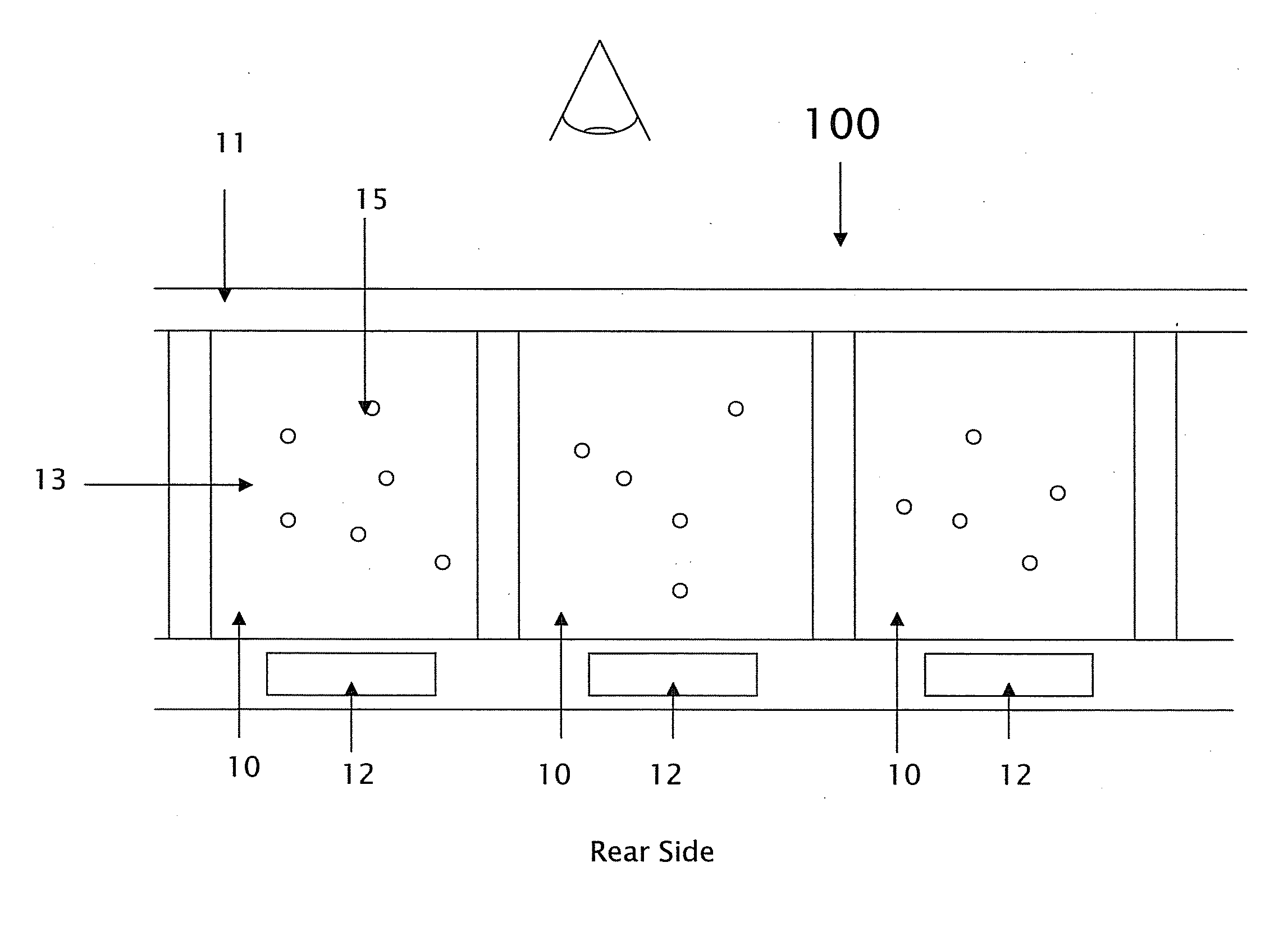
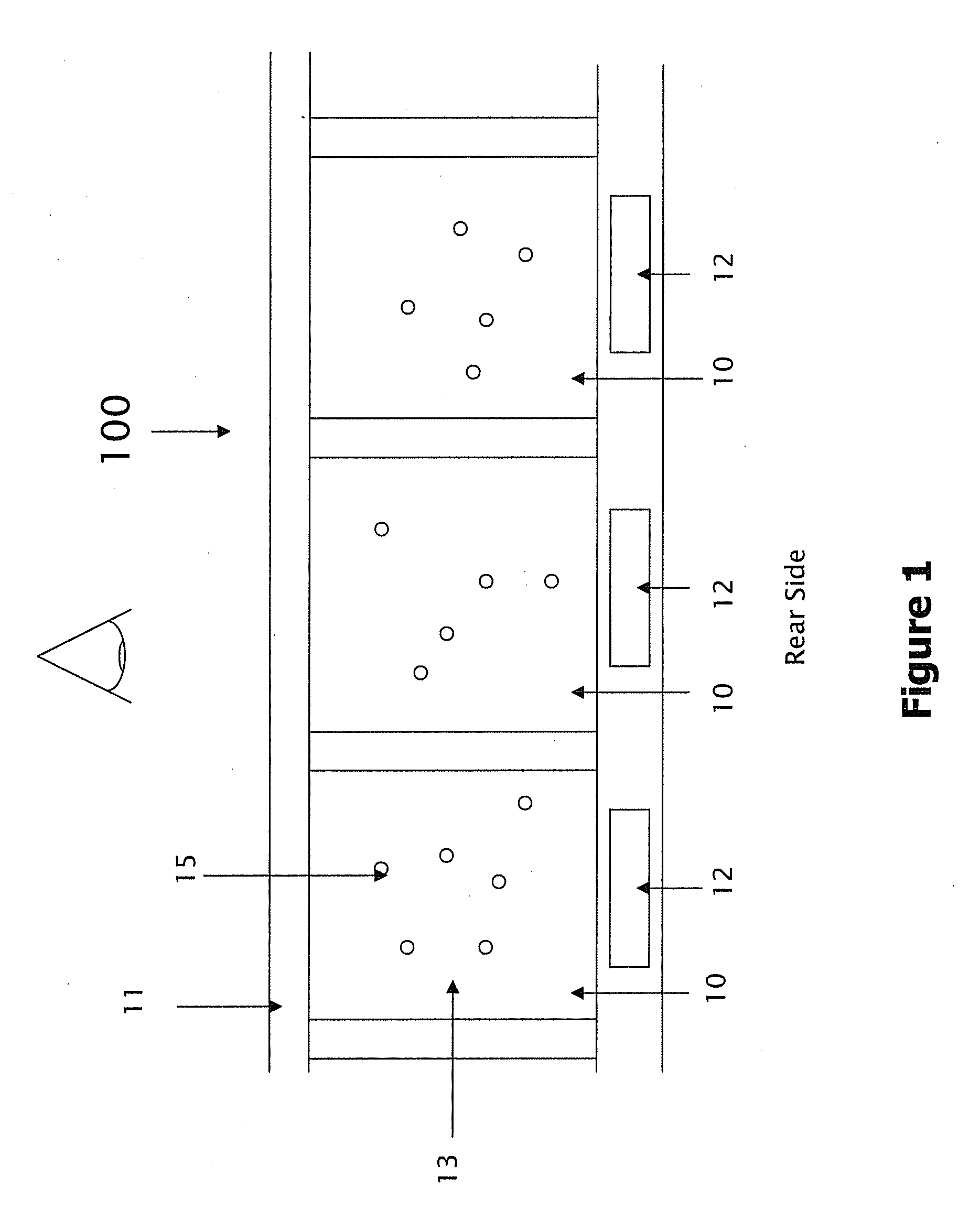
[0020]FIG. 1 illustrates a typical electrophoretic display 100 comprising a plurality of electrophoretic display cells 10. In FIG. 1, the electrophoretic display cells 10, on the front viewing side indicated with the graphic eye, are provided with a common electrode 11 (which is usually transparent and therefore on the viewing side). On the opposing side (i.e., the rear side) of the electrophoretic display cells 10, a substrate includes discrete pixel electrodes 12. Each of the pixel electrodes defines an individual pixel of the electrophoretic display. In practice, a single display cell may be associated with one discrete pixel electrode or a plurality of display cells may be associated with one discrete pixel electrode.

[0021]An electrophoretic fluid 13 comprising charged pigment particles 15 dispersed in a solvent is filled in each of the display cells. The movement of the charged particles in a display cell is determined by the driving voltage associated with the display cell in ...


PUM


Abstract

The present invention is directed to driving waveforms and a driving method for an electrophoretic display. The method and waveforms have the advantage that the changes in the driving voltages due to the shift are minimized. In addition, the overall driving time for the waveforms is also shortened due to the shortened driving frames. There are no additional data points required as the number of the driving frames remains the same. Therefore, the power consumption is nearly identical with the waveform having driving frames of a fixed frame time.

Description

[0001]This application claims priority to U.S. Provisional Application No. 61 / 295,628, filed Jan. 15, 2010; the content of which is incorporated herein by reference in its entirety.TECHNICAL FIELD[0002]The present invention relates to driving waveforms and a driving method for an electrophoretic display.BACKGROUND OF THE INVENTION[0003]An electrophoretic display (EPD) is a non-emissive device based on the electrophoresis phenomenon of charged pigment particles suspended in a solvent. The display usually comprises two plates with electrodes placed opposing each other and one of the electrodes is transparent. A suspension composed of a colored solvent and charged pigment particles dispersed therein is enclosed between the two plates. When a voltage difference is imposed between the two electrodes, the pigment particles migrate to one side or the other, causing either the color of the pigment particles or the color of the solvent to be seen, depending on the polarity of the voltage dif...

Claims


Application Information

Patent Timeline
IPC IPC(8): G09G5/00G09G3/34
CPCG09G3/344G09G2310/06G09G2300/08
Inventor LIN, CRAIGCHAN, BRYAN
Owner E INK CALIFORNIA
Learn More