
Input apparatus

Active Publication Date: 2011-07-14
KYOCERA CORP
View PDF26 Cites 159 Cited by
  • Summary
  • Abstract
  • Description
  • Claims
  • Application Information

AI Technical Summary

Benefits of technology

[0024]Accordingly, an object of the present invention in consideration of such conditions is to provide an input apparatus capable of reducing incorrect operations by a user in receiving pressure inputs to a plurality of adjacent input objects on a touch panel mounted on, for example, a mobile phone.

Problems solved by technology

Accordingly, it is generally not possible to change a physical arrangement of keys, once defined, later.
If such terminals have keys fixedly arranged, it may inconvenience the user significantly in using particular functions.
However, the input apparatus with the touch panel has a specific problem because of its configuration to have the input unit and the display unit on the same screen and to receive the intuitive operation input.
That is, although the touch panel can constitute the display unit arranging the input objects as desired, it is difficult for the user to determine a boundary between an input object and another area by a tactile sensation because a surface of the input unit is generally flat.
In addition, since the user directly touches the input unit with a finger or a stylus in order to input to the touch panel, the input object is covered at the moment of the pressure input, preventing the user from visually confirming the input object to receive the operation input.
Accordingly, since the user cannot determine, with a feeling on the finger, whether the finger is touching an input object, there is always a possibility to press an unintended position.
That is, there is a risk of pressing a position elsewhere than an intended input object by pressing a position slightly off from it or a risk of pressing another input object adjacent to the intended input object.
When pressing an input object intended with a finger, a risk of unintended input becomes higher, as the input object is covered with the finger.
Moreover, if an important processing or operation being performed is stopped because of the unintended operation, it may cause an unrecoverable situation.

Method used


Image

  • Input apparatus
  • Input apparatus
  • Input apparatus

Examples


Embodiment Construction

[0048]Embodiments of the present invention will be described with reference to the accompanying drawings. In the following embodiments, a mobile phone is used as an exemplary mobile terminal with an input apparatus according to the present invention. However, the mobile terminal to which the input apparatus according to the present invention is applicable is not only the mobile phone but also any mobile terminal having a touch panel such as a PDA, for example. In addition, the present invention is applicable not only to the mobile terminal having the touch panel but also to any input terminal having the touch panel such as ATMs of a bank and ticket vending machines at a train station as stated above.

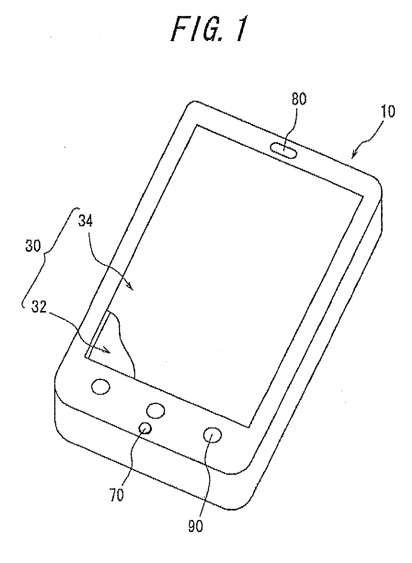
[0049]FIG. 1 is an external perspective view illustrating a schematic configuration of a mobile phone 10 having an input apparatus according to an embodiment of the present invention. The mobile phone 10 has a display unit 32, a part of which is displayed in the figure, on a front face o...


PUM


Abstract

An input apparatus has a display unit for displaying an input object, an input unit for receiving a pressure input to the input object, a load detection unit for detecting a pressure load on the input unit, and a control unit for controlling to receive the pressure input if the pressure load detected by the load detection unit satisfies a load standard. The control unit controls such that a load standard for receiving the pressure input to the input object is different from a load standard for receiving a pressure input to another input object adjacent to the input object.

Description

CROSS REFERENCE TO RELATED APPLICATION[0001]This application claims priority to and the benefit of Japanese Patent Application No. 2008-331056 filed on Dec. 25, 2008, the entire contents of which are incorporated herein by reference.TECHNICAL FIELD[0002]The present invention relates to input apparatuses, and more particularly, to input apparatuses having touch panels.BACKGROUND ART[0003]For mobile terminals such as mobile phones, various input apparatuses used by users to operate the terminals have been developed according to functions and usages of each of the terminals. In many cases, an input apparatus has mechanical keys or buttons arranged in advance on a surface of a body such that a user performs an input operation by directly pressing a finger or the like to the keys.[0004]The mechanical keys (for example, a numerical keypad) of the input apparatus of the terminal are normally arranged in advance to suit a main usage of the terminal. Accordingly, it is generally not possible...

Claims


Application Information

Patent Timeline
IPC IPC(8): G06F3/041G06F3/0488
CPCG06F3/016G06F3/041G06F2203/04105G06F2203/014G06F3/04886G06F3/14G06F3/0488
Inventor AONO, TOMOTAKE
Owner KYOCERA CORP
Learn More