
Crop catching apparatus and crop harvesting machine employing the same

Inactive Publication Date: 2011-07-14
SIDHU RUPINDER SINGH +1
View PDF12 Cites 11 Cited by
  • Summary
  • Abstract
  • Description
  • Claims
  • Application Information

AI Technical Summary

Benefits of technology

[0005]Certain features, aspects and examples disclosed herein are directed to crop-catching apparatuses configured to divert a direction of fall of crops such as may be adapted for use in a crop harvesting machine. More particularly, certain features, aspects and examples are directed to a crop-catching apparatus for use in

Problems solved by technology

A drawback of existing crop harvesting machines is their inefficiency in preventing dropped crops which are not effectively collected by the machine.

Method used


Image

  • Crop catching apparatus and  crop harvesting machine employing the same
  • Crop catching apparatus and  crop harvesting machine employing the same
  • Crop catching apparatus and  crop harvesting machine employing the same

Examples


Embodiment Construction

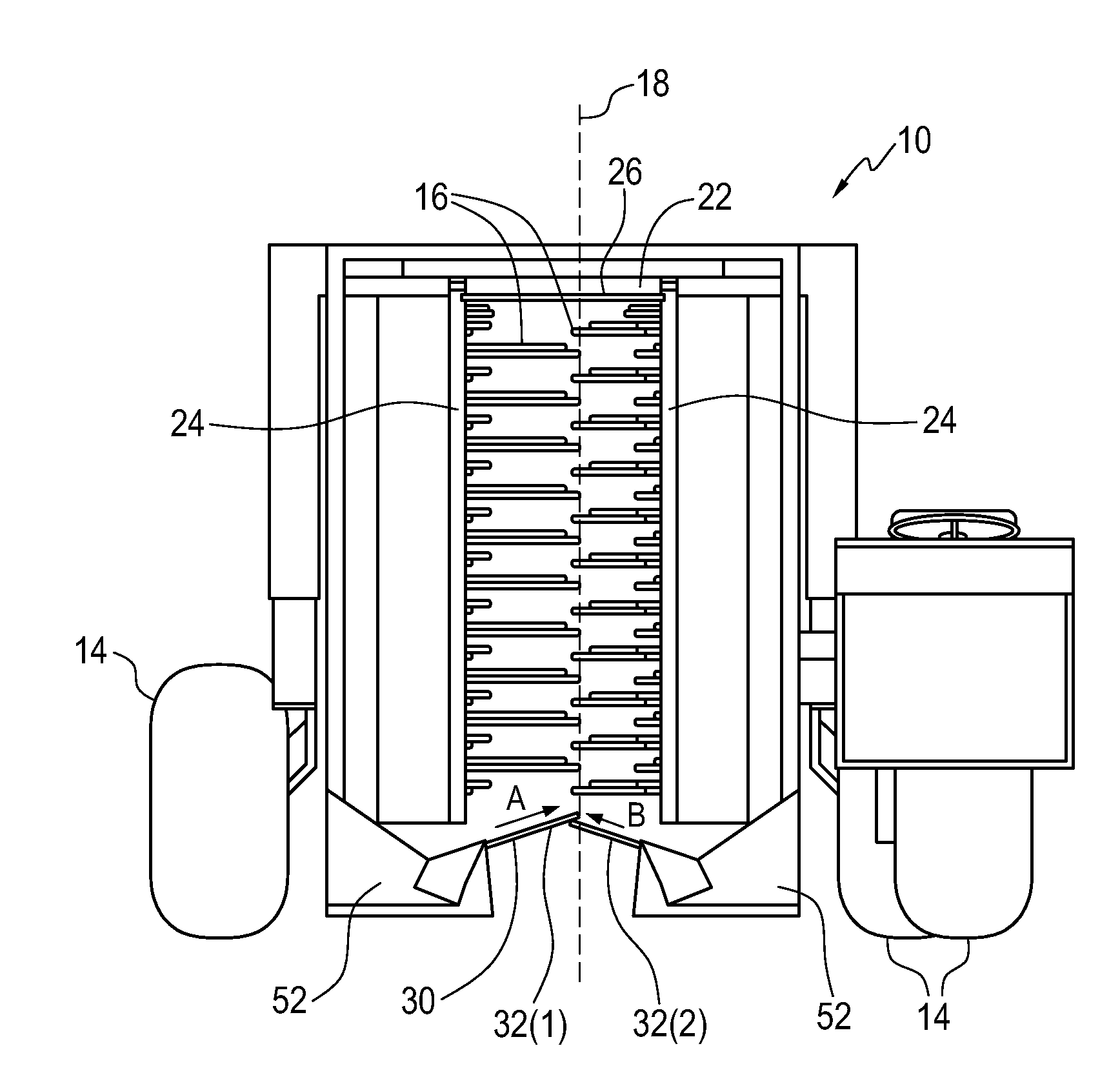
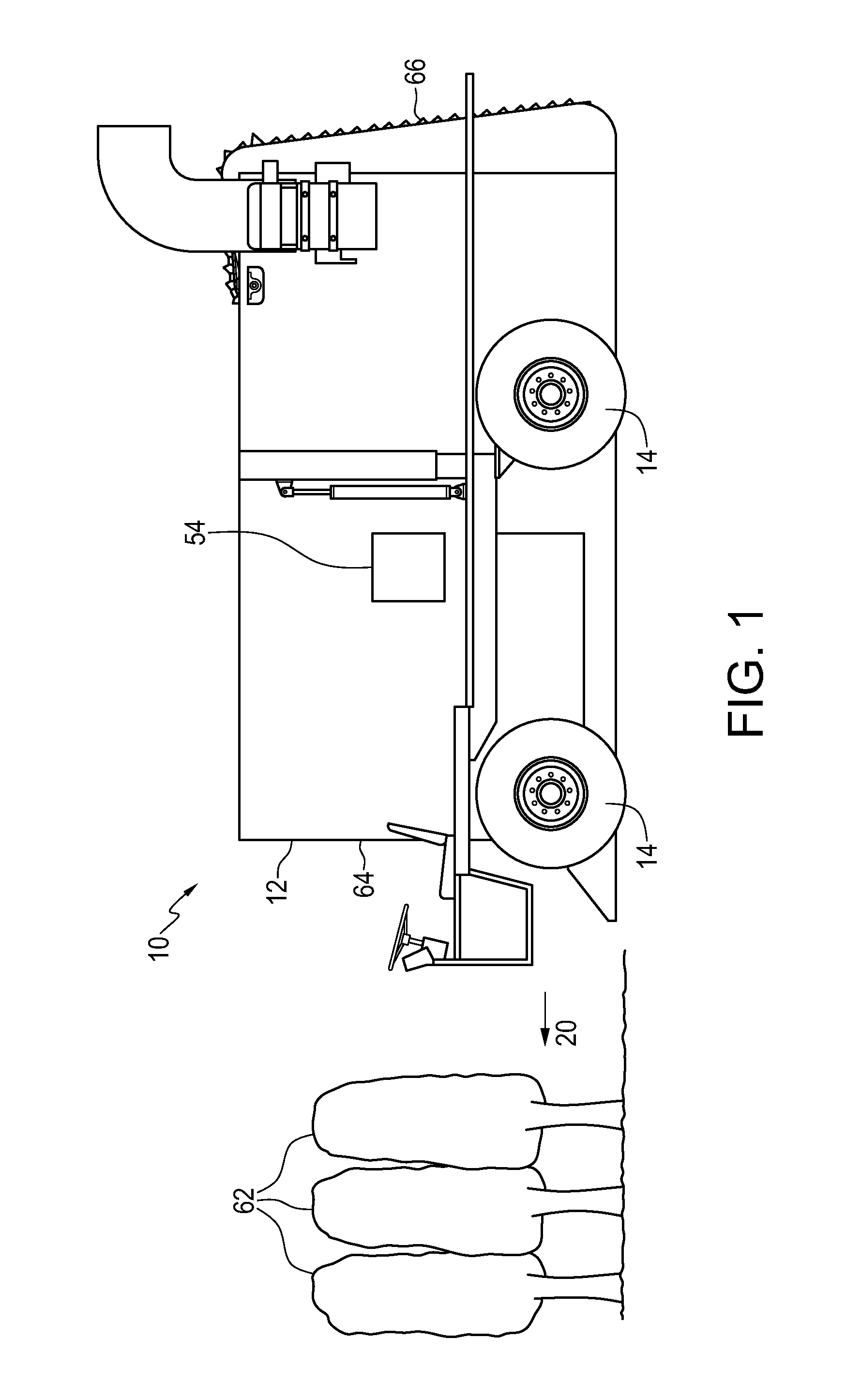
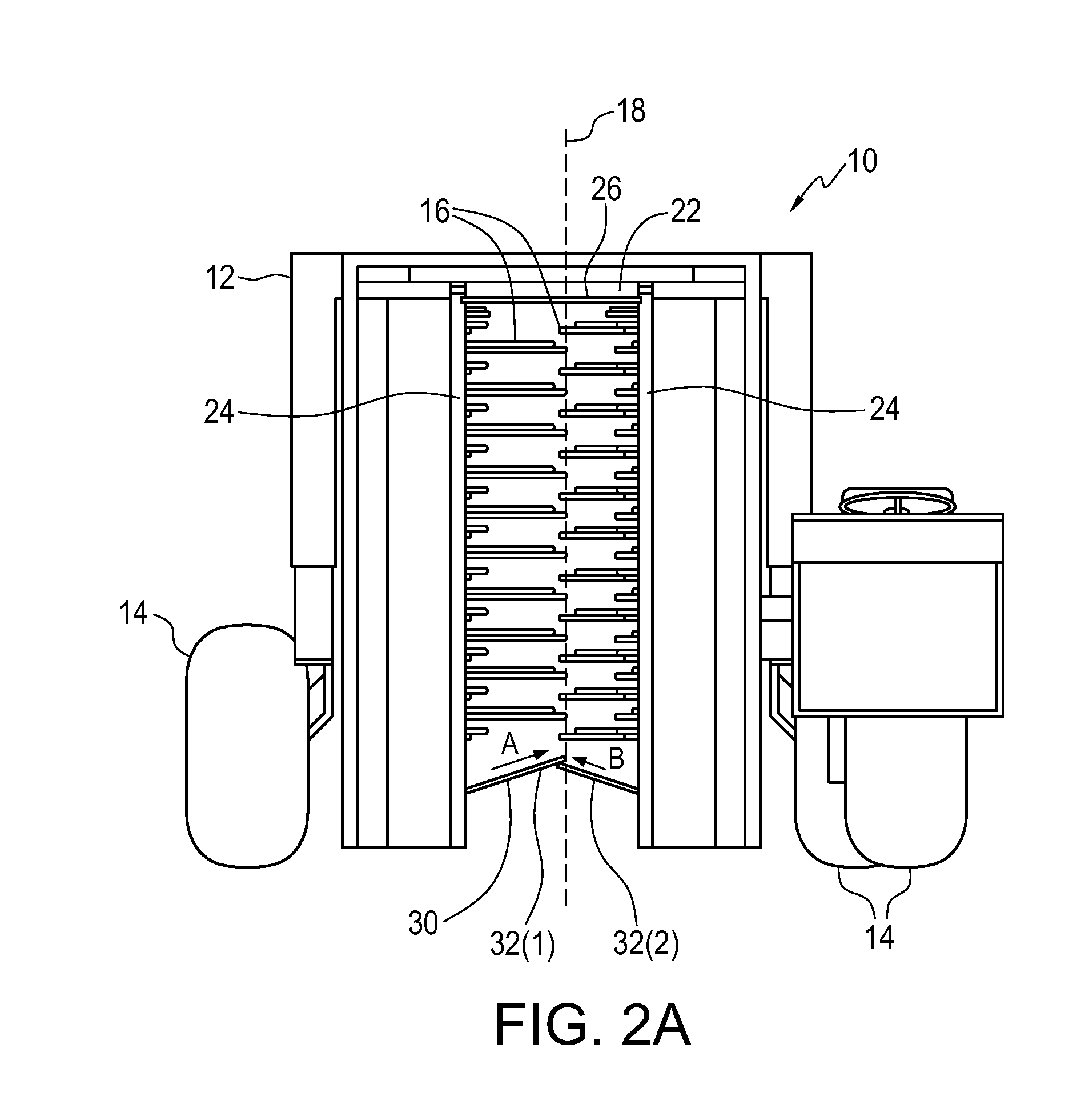
[0026]In one embodiment, the present invention comprises a crop catching apparatus that provides for utilizing output of a fluid flow to reduce loss of crops and thereby improve the efficiency of crop collection during harvesting. In one embodiment, the crop-catching apparatus may be retrofitted to existing crop harvesting machines, or included as part of a novel crop harvesting machine as disclosed herein. More specifically, in one embodiment, the crop catching apparatus includes one or more fluid conduits defined within or between one or more plate members to receive, carry, and output one or more fluids such as to divert a direction of fall of the crops as they fall onto or adjacent to the fluid outputs of the plate members. The diversion of crop fall feature as disclosed herein in the present crop catching apparatus / crop harvesting machine provides a significant improvement over conventional crop harvesting machines, where severed crops that would have otherwise been lost by dir...


PUM


Abstract

A crop-catching apparatus for use in a crop harvesting machine is disclosed, including one or more plate members and one or more fluid conduits. The plate member) each have a surface adapted for catching falling crops, a front end and a back end, and a leading edge. The back end(s) are configured to pivotally mount on the crop harvesting machine. The front end(s) are configured to rest at a higher elevation with respect to the pivotally mounted back end(s). The conduit(s) are defined within at least one of the plate member(s) for carrying one or more fluids, and include one or more fluid inlets defined on the at least one of the plate member(s) for receiving the one or more fluids; and one or more fluid outlets defined on the at least one of the plate member(s) running at least partially along the leading edge(s) of the at least one of the plate member(s). The fluid outlet(s) are configured such that the one or more fluids exit therefrom to divert a direction of fall of the crops. A crop harvesting machine employing a crop-catching apparatus is also disclosed.

Description

1. TECHNICAL FIELD[0001]The present invention relates generally to crop catching apparatuses for use in crop harvesting machines. More particularly, the present invention relates to improved crop catching apparatuses with fluid conduits defined in catcher plate members, and to crop harvesting machines employing the same.2. BACKGROUND OF THE INVENTION[0002]A conventional crop harvesting machine suited for harvesting berries or other bush-grown or small tree-grown crops such as coffee beans, etc., typically includes a mobile frame that is supported by wheels and set into motion via manual or motorized propulsion. To harvest crops, the frame of the crop harvesting machine is maneuvered over a crop plant such as a bush or small tree, and straddles the crop plant in the interior cavity of the machine. The cavity of the frame in the machine is typically in an inverted U-shape formed by a lateral interior roof surface joined at two ends by two opposing interior vertical side surfaces. To c...

Claims


Application Information

Patent Timeline
IPC IPC(8): A01D46/00
CPCA01D46/28
Inventor SIDHU, RUPINDER SINGHCHEEMA, PARMINDER
Owner SIDHU RUPINDER SINGH
Learn More