Transmit-receive radio frequency front end integrated circuits for laptop computer applications
- Summary
- Abstract
- Description
- Claims
- Application Information
AI Technical Summary
Benefits of technology
Problems solved by technology
Method used
Image
Examples
first embodiment
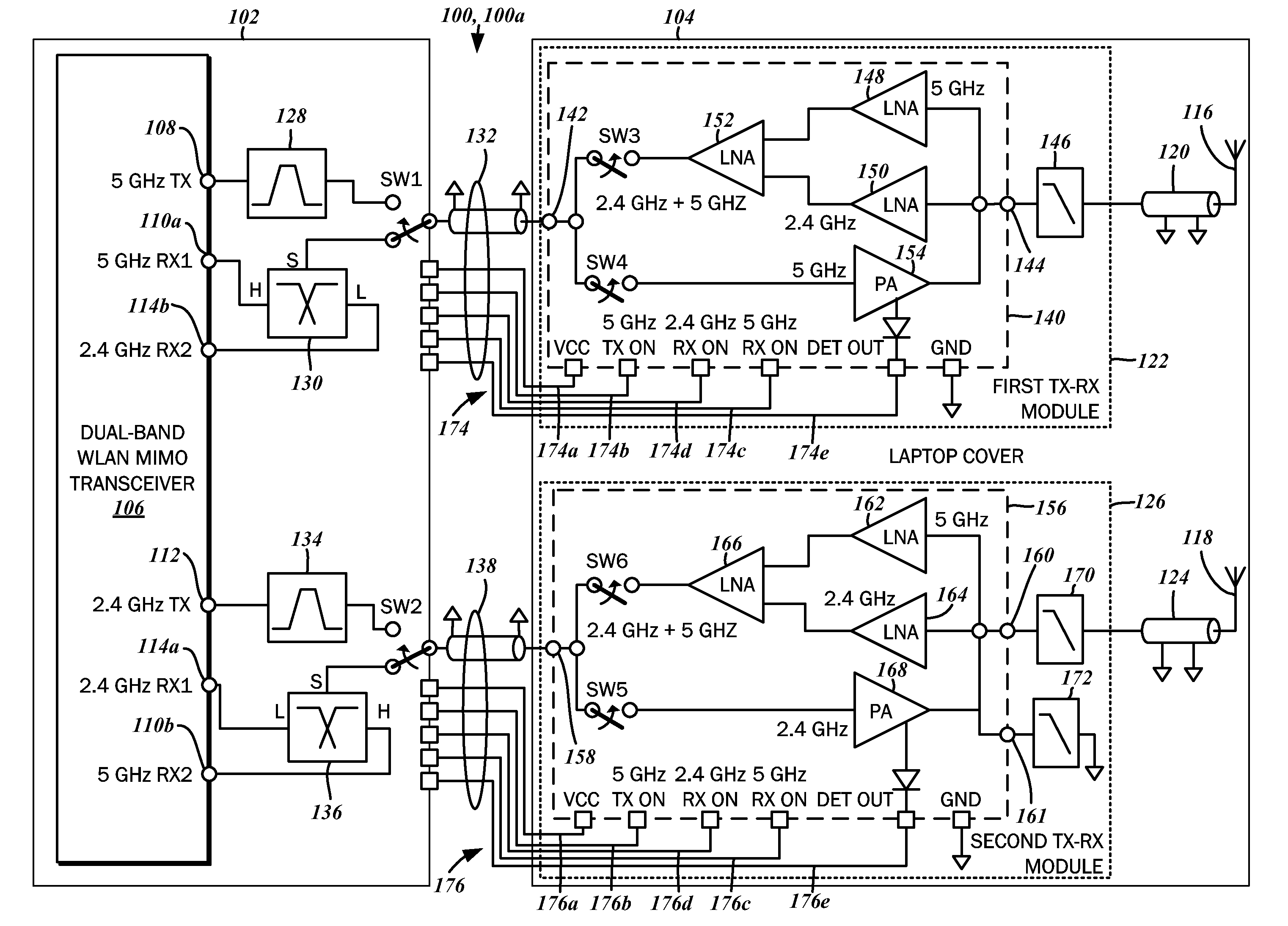
[0032]The block diagram of FIG. 1 illustrates an RF communications system 100a with a first operating frequency band and a second operating frequency band. By way of example, the RF communications system 100 in general is a wireless local area network (WLAN) module of a computer system, which is preferably, though optionally, a mobile device such as a laptop computer. Though specific features related to this form factor will be described, it will be recognized that the RF communications system 100 may be utilized in any computing device that incorporates wireless networking features. Various embodiments of the RF communications system 100 are understood to be compliant with the IEEE 802.11 standard, which defines an operating frequency band of 5 GHz as well as 2.4 GHz. These correspond to the respective first and second operating frequency bands.
[0033]A laptop computer typically has a flip or clamshell form factor comprised of a body with a hinged cover. The body includes the main b...
third embodiment
[0068]the RF communications system 100c, however, contemplates a set of control lines 202 that are associated with the second interconnect cable 138. Again, there is a first control line 202a that is connected to the first operating frequency band transmit enable port 188. Also, the transmit power detector output ports 198, 200 are connected to a second control line 202b. The bias supply voltage from VCC 204, however, is delivered through the signal transmission line of the second interconnect cable 138, further reducing the number of control lines extending from the body segment 102 to the cover segment 104.
[0069]Referring now to FIG. 7, details pertaining to the second interconnect cable 138 capable of carrying the bias supply voltage will be considered. There is a coaxial center conductor 206 that extends along the length of the cable 138. As the coaxial center conductor 206 carries RF signals as well as the bias supply voltage, it is constructed of an electrically conductive mat...
second embodiment
[0074]With reference to the schematic diagram of FIG. 9, and in particular, to FIGS. 9A and 9B, the front end circuit 220b may be utilized with a transceiver 106 that has a receive port and a transmit port for each operating frequency. In this regard, the front end circuit 220b has a first operating frequency band transmit port 226, a first operating frequency band receive port 228, a second operating frequency band transmit port 230, and a second operating frequency band receive port 232. The front end circuit 220b is connected to a single antenna, and thus has one antenna port 224. In general, the front end circuit 220b can be segregated into a first operating frequency band block 234, shown in FIG. 9A, and a second operating frequency block 236, shown in FIG. 9B.
[0075]The first operating frequency band block 234 may be further segregated into a first operating frequency band transmit block 234a, and a first operating frequency band receive block 234b. The first operating frequenc...
PUM
 Abstract
Description
Claims
Application Information
 - R&D
- Intellectual Property
- Life Sciences
- Materials
- Tech Scout
- Unparalleled Data Quality
- Higher Quality Content
- 60% Fewer Hallucinations
Browse by: Latest US Patents, China's latest patents, Technical Efficacy Thesaurus, Application Domain, Technology Topic, Popular Technical Reports.
© 2025 PatSnap. All rights reserved.Legal|Privacy policy|Modern Slavery Act Transparency Statement|Sitemap|About US| Contact US: help@patsnap.com


