Audiovisual multi-room support

a multi-room, audiovisual technology, applied in closed-circuit television systems, home automation networks, television systems, etc., can solve the problems of user missing parts of the broadcast, user being unable to organise and access content as freely as they might wish, and unable to easily achieve. , to achieve the effect of smooth transition for users

Active Publication Date: 2011-06-30
SATURN LICENSING LLC
View PDF19 Cites 31 Cited by
  • Summary
  • Abstract
  • Description
  • Claims
  • Application Information

AI Technical Summary

Benefits of technology

[0017]According to this aspect, the invention allows for the transferral of the output of audiovisual content or media across a network, to a location selected by a user from the original output location. This allows a user to ‘send’ the content to a new location which they intend to move to (for example another room in a house), so that the content will be waiting for them when they arrive. This is advantageous because it avoids the user needing, for example, to either re-tune to a broadcast at the destination or to physically transfer the audiovisual content (for example a DVD) to the new location and then re-locate the playback position at which the playback was interrupted when the user changed locations. Also, the automatic transfer avoids the need for the user to search for and access any information which may be stored on the network in connection with a previous viewing of the content in order to start playback from the interruption point. Instead, the system responds to the user's original input so that when they arrive at the destination the content is awaiting playback from the interruption point.
[0019]According to these embodiments, the invention allows for the transfer of content to devices which are not in a full power state at the time the transfer is initiated by the user. In UPnP networks, devices in a low power or ‘sleep’ mode remain registered with the network and can be awoken by a message from the network. The present invention uses this functionality to allow the user to transfer the audiovisual content to the device in a low power mode, turning the device on into full power mode, so that playback of the content can begin as soon as possible at the destination. That is, there is no delay because the user has to go to the destination and put the destination device into full 
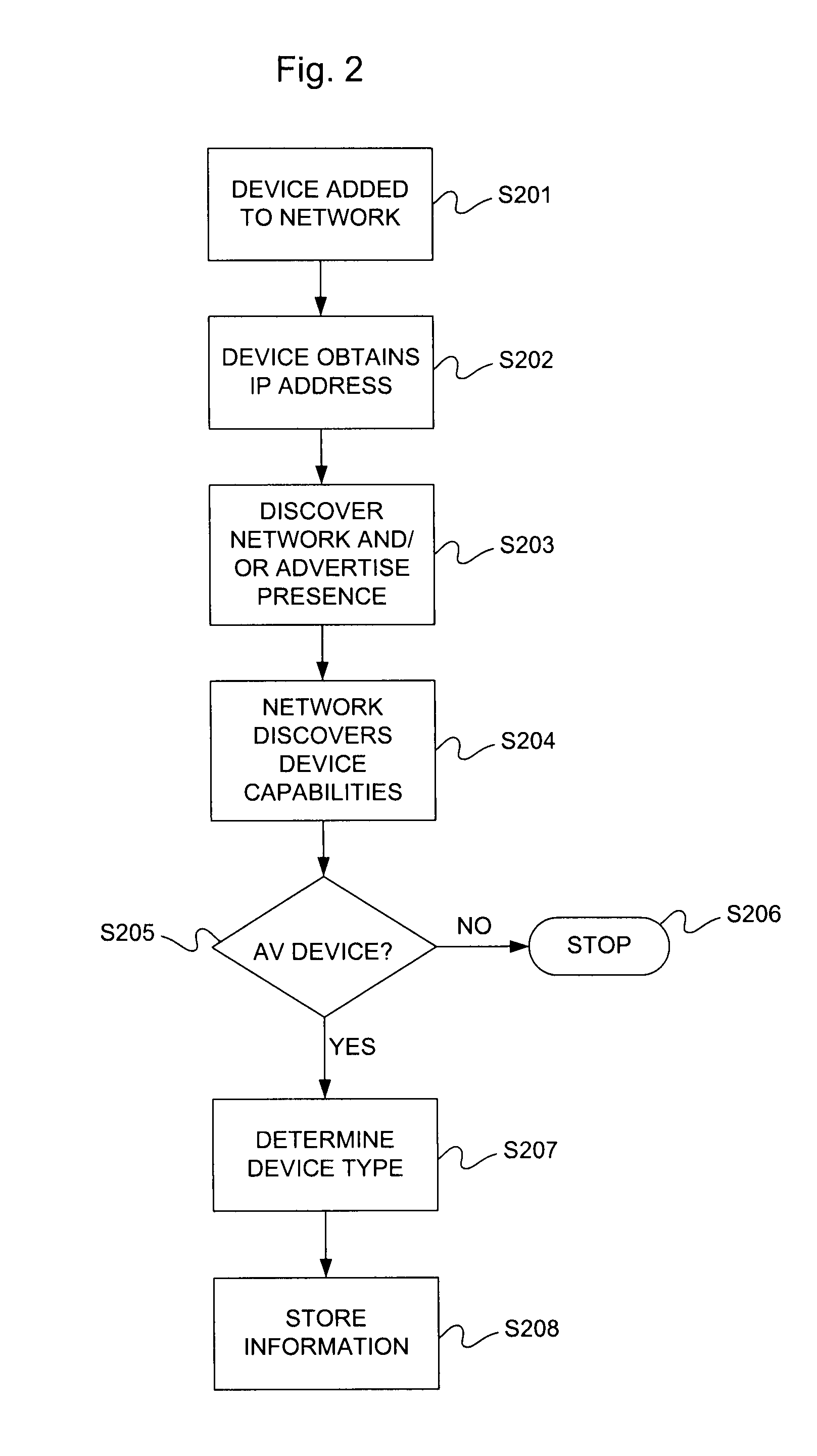
power mode. Conventional UPnP networks do not ‘remember’ devices which have been completely turned off. When a device is turned off, it sends a ‘leaving network’ message, so that control points on the network remove the device from the network map. This is a problem because it means that the devices cannot be accessed by the network, and therefore transfer of content to the device cannot be arranged. In the present invention, devices which are turned off do not send a ‘leaving network’ message, so that the device remains on the network map. In some embodiments, the device may send a ‘turning off’ message to the network, but this only serves to inform the network of the power state of the device, and does not result in the device being removed from the network map. As a result, although communication cannot be established with the device whilst it is off, the network remains ‘aware’ of the device when it is off, and can therefore schedule transfers of audiovisual content to the device, to occur once the device is turned on. This allows a user to arrange a transfer of audiovisual content from a first device, and for the transfer to be completed by turning on the second, destination, device without having to then perform any further steps to set up communication of the destination device with the first device.
[0020]Preferably the method further comprises: ceasing the output of the audiovisual content on the first output device; and the outputting of the audiovisual content on the second output device occurring from the point at which output was ceased on the first output device. This allows for the playback of content at the second output device to be started at the point playback was interrupted on the first device. This avoids the user having to search for the playback position in the audiovisual content at the second device, enabling a smooth transition for the user when switching playback devices.
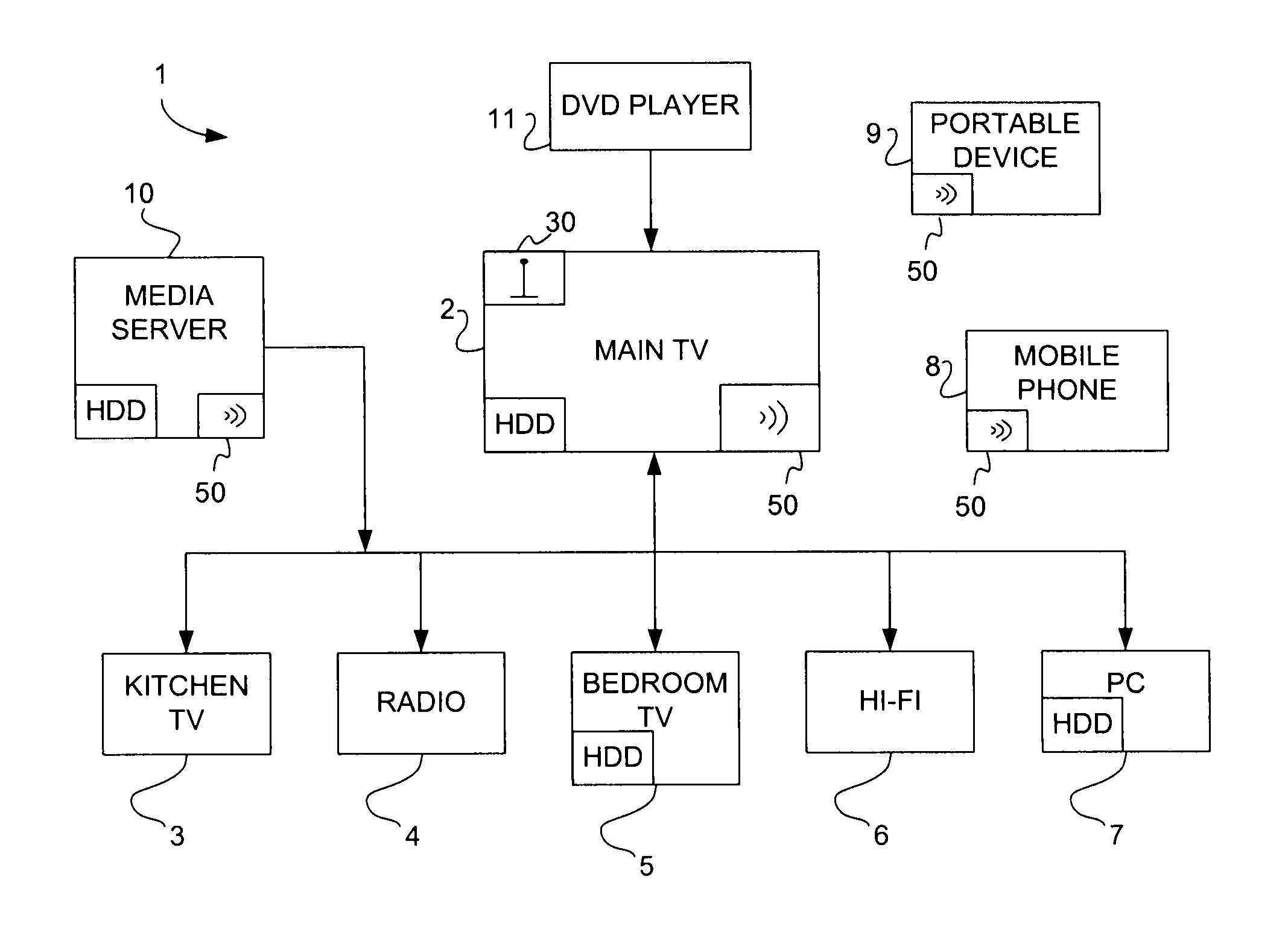
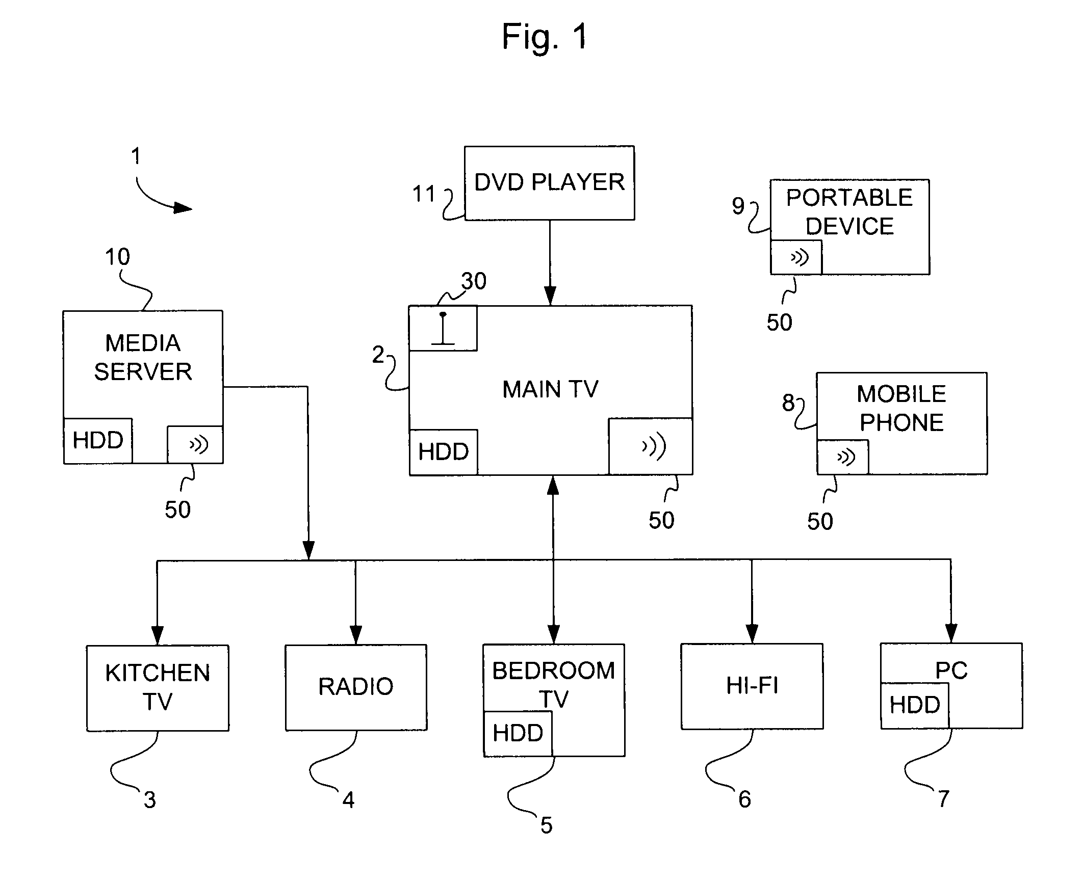
[0024]Preferably, the method further comprises: determining which devices associated with the network are suitable for outputting the audiovisual content, and informing the user of the suitable devices, at the first output device, before the user selects the second output device. Further, at least one of the first and second output devices may be a television set, a display screen, a receiver for signals representing audio information, a hi-fi, a computer, a set top box, a media streamer device, a gaming console or a media player. This prevents the user being presented with the option of transferring the audiovisual content to a device on the network which is not capable of outputting the content. This may be achieved by either only informing the user of the suitable devices, or may be achieved by informing the user of all devices associated with the network with an indication of those devices which are suitable for the transfer.
[0025]Preferably, the network is a network in accordance with the Universal Plug and Play standard. UPnP networks allow for ease of set-up, which is further enhanced by DLNA. As such UPnP networks are well suited for the home environment. However, the invention may be implemented on any network architecture.

Problems solved by technology

As audiovisual content becomes available from more sources and in more formats, it becomes difficult for a user to organise and access the content as freely as they might wish.
One problem that a user may face is that they may start viewing or listening to content at one location, and then either be interrupted or simply wish to change location.
At present, this cannot easily be achieved.
If the film is broadcast content, the user may miss part of the broadcast as they change rooms.
Also, if the television device in the kitchen is off, it may take time to re-connect to the network and access the desired content.
All of these issues mean that a user's enjoyment of the content is impaired, as it is difficult to transfer content between devices mid-way through content playback.
This still leaves a burden on the user to access the media, which is especially annoying if the change in location is not accompanied by a long pause (such as when a user changes rooms).

Method used


Image

  • Audiovisual multi-room support
  • Audiovisual multi-room support
  • Audiovisual multi-room support

Examples


Embodiment Construction

[0037]The present invention can be implemented in connection with existing network architectures. Examples of such architectures include UPnP and DNLA. The following examples are based on UPnP and DNLA networks. Therefore, UPnP and DNLA are discussed below.

[0038]UPnP is fully described in the UPnP standards, available from www.upnp.org. Of background relevance to the invention are the documents UPnP Device Architecture 1.1, of 15 Oct. 2008; UPnP AV Architecture 0.83, of 12 Jun. 2002 and UPnP Low Power Architecture, of 4 Apr. 2007. However, the most relevant aspects of UPnP are described below.

[0039]The basic building blocks of a UPnP network are devices, services and control points.

[0040]A UPnP device is a container of services and nested devices. For instance, a VCR device may consist of a tape or disc transport service, a tuner service, and a clock service. A TV / VCR combination device would consist not just of services, but a nested device as well.

[0041]Different categories of UPn...


PUM


Abstract

The invention relates to providing audiovisual content on a network, and methods of transferring the audiovisual content between devices attached to the network. The methods involve accepting user input, at a first output device that is outputting audiovisual content, to select a second output device from the output devices associated with the network and subsequently outputting the audiovisual content on the second output device that is selected.

Description

CROSS-REFERENCE TO RELATED APPLICATIONS[0001]This application is based upon and claims the benefit of priority from British Application No. 0922742.2 filed 31 Dec. 2009, the entire contents of which are incorporated by reference.BACKGROUND OF THE INVENTION[0002]1. Field of the Invention[0003]The present invention relates to providing audiovisual content on a network, and methods of transferring the audiovisual content between devices attached to the network.[0004]2. Description of the Related Art[0005]It is now common for people to have access to wide range of audiovisual content. Audiovisual content or media includes, but is not limited to, content such as music, films and television programming. The content may either be available on a form of physical storage media, such as an optical disc or a hard drive, or available ‘live’ or in ‘real time’ via broadcasting services such as television, radio, the interne or on-demand services.[0006]As audiovisual content becomes available from...

Claims


Application Information

Patent Timeline
IPC IPC(8): H04N7/18
CPCH04N21/4333H04N21/43622H04N21/43615H04N21/436H04L12/282
Inventor DODD, KEVIN
Owner SATURN LICENSING LLC
Why Eureka
Try Eureka