
Efficiency measuring circuit for dc-dc converter which calculates internal resistance of switching inductor based on duty cycle

a technology of switching inductor and efficiency measurement, which is applied in the direction of power supply testing, instruments, machine control, etc., can solve the problems of inability to use a sense resistor to measure output current, and inability to accurately measure the efficiency of a dc-dc converter. to achieve the effect of computing the efficiency of the dc-dc converter

Active Publication Date: 2011-06-30
ANALOG DEVICES INT UNLTD
View PDF13 Cites 26 Cited by
  • Summary
  • Abstract
  • Description
  • Claims
  • Application Information

AI Technical Summary

Benefits of technology

[0007]An efficiency measuring circuit may measure the efficiency of a DC-DC converter having a switching inductor with an internal DC resistance and a plurality of electronic switches that control current through the inductor. A duty cycle circuit may measure the duty cycle of current flowing through one of the electronic switches. A current sense circuit may measure the current flowing through o

Problems solved by technology

Accurately measuring a low-loss, step-down DC-DC converter's efficiency in situ can be challenging.
The large output currents and low output voltages required from some high-efficiency step-down DC-DC converters can make the use of a sense resistor to measure output current unattractive.
Relying instead upon the internal resistance of the switching inductor can also be problematic.
Thus, it can be difficult to accurately measure efficiency because of difficulties in accurately measuring output current.

Method used


Image

  • Efficiency measuring circuit for dc-dc converter which calculates internal resistance of switching inductor based on duty cycle
  • Efficiency measuring circuit for dc-dc converter which calculates internal resistance of switching inductor based on duty cycle
  • Efficiency measuring circuit for dc-dc converter which calculates internal resistance of switching inductor based on duty cycle

Examples


Embodiment Construction

[0026]Illustrative embodiments are now discussed. Other embodiments may be used in addition or instead. Details which may be apparent or unnecessary may be omitted to save space or for a more effective presentation. Conversely, some embodiments may be practiced without all of the details which are disclosed.

Step-Down DC-DC Converter

[0027]Apparatus and methods for accurately measuring the efficiency of step down DC-DC converters. The measurement may be made without requiring a precise output current sense resistor, known load current, or a known change in load current. A precise input current sense resistor may be used, but the associated power loss may be minimal. The apparatus and methods may also be used in connection with step up DC-DC converters, as well as multiphase applications.

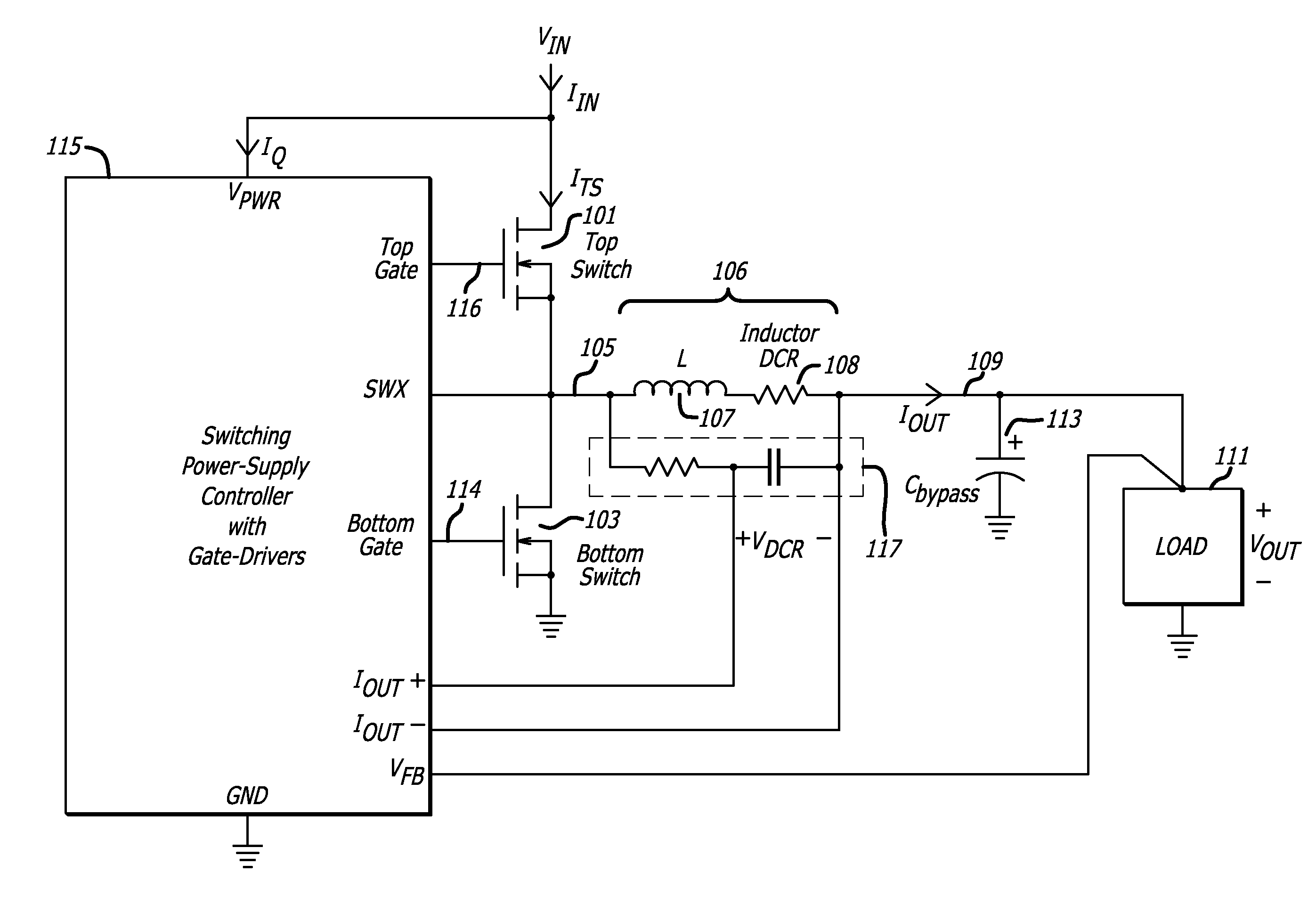
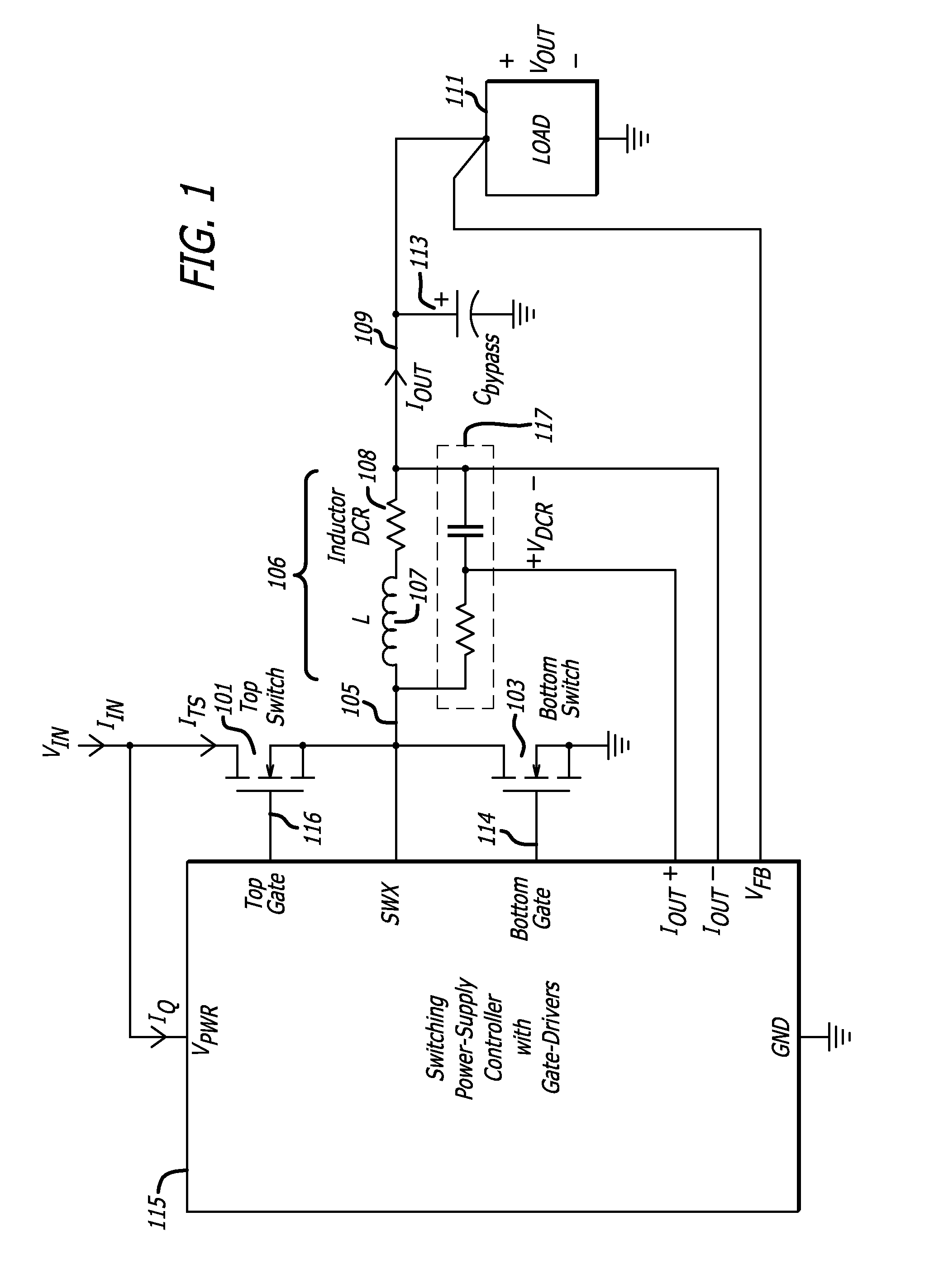
[0028]FIG. 1 is an example of a step-down switching DC-DC converter. This converter architecture may utilize a top switch 101 and a bottom switch 103 to drive a switching terminal 105 of a switching in...


PUM


Abstract

An efficiency measuring circuit may measure the efficiency of a DC-DC converter having a switching inductor with an internal DC resistance and a plurality of electronic switches that control current through the inductor. A duty cycle circuit may measure the duty cycle of current flowing through one of the electronic switches. A current sense circuit may measure the current flowing through one of the electronic switches. An inductor voltage sensor circuit may measure the voltage across the inductor. A computation circuit may compute the internal DC resistance of the switching inductor based in part on the duty cycle measured by the duty cycle circuit and the current measured by the current sense circuit. The computation circuit may also compute the efficiency of the DC-DC converter.

Description

CROSS-REFERENCE TO RELATED APPLICATION[0001]This application is based upon and claims priority to U.S. Provisional Patent Application No. 61 / 290,116 entitled “LOW-LOSS, HIGH-ACCURACY EFFICIENCY METER FOR STEP-UP AND STEP-DOWN SWITCHING POWER SUPPLIES,” filed Dec. 24, 2009, attorney docket number 081318-0249. The entire content of this application is incorporated herein by reference.BACKGROUND[0002]1. Technical Field[0003]This disclosure relates to switching power supplies and, more particularly, measuring the efficiency of switching power supplies.[0004]2. Description of Related Art[0005]Determining the efficiency of a switching power-supply in situ is an area of growing interest. An incremental reduction in overall power consumption and / or power consumption cost for a plurality of DC-DC converters and their associated loads may be realized by continuously optimizing load allocations in response to changes in the efficiency of one or more of the individual DC-DC converters. In order...

Claims


Application Information

Patent Timeline
IPC IPC(8): G05F1/10
CPCG01R1/203G01R19/0092H02M2001/0009H02M3/156G01R31/40H02M1/0009
Inventor GARDNER, ANDREW JOSEPHMANLOVE, GREGORY JONCHIACCHIA, ROBERT C.WITTE, HELLMUTH STEPHEN
Owner ANALOG DEVICES INT UNLTD
Learn More