
Dental articulating paper forceps

Inactive Publication Date: 2011-06-23
SOLANO MILDRED +1
View PDF3 Cites 9 Cited by
  • Summary
  • Abstract
  • Description
  • Claims
  • Application Information

AI Technical Summary

Benefits of technology

[0005]The dental forceps of the present invention constitutes a significant improvement over existing forceps, in that it is conveniently utilized and readily maneuverable within the patient's mouth. Its configuration makes positioning and placement of articulating paper between the interproximal surface of a crown, bridge or dental appliance and a tooth easier and faster, while ensuring less patient discomfort. The forceps also serve to hold the paper more firmly in position.
[0006]These and other objectives are accomplished by the present invention, dental forceps for holding dental articulating paper having dual elongated spring arms, moveable toward and away from each other. The spring arms each have a lower handle section, an intermediate section extending from the lower handle section, and an upper section with a cantilevered member extending from the top end of the intermediate section. Clamping support arms extend outward from and perpendicular to the cantilevered member of each of the spring arms. The support arms have jagged surfaces which enhance the paper holding capability of the spring arms. When the spring arms are fully biased away from each other, the support arms are closed and articulating paper is held therebetween. When the lower handle sections of the spring arms are moved together, the support arms open to release the paper.

Problems solved by technology

However, this and similar configured forceps have inherent handicaps in that they are difficult to maneuver and thus prevents the dental professional from efficiently and easily positioning articulating paper within a patient's mouth.
This is especially the case when paper needs to be inserted near the back, more hard to get to molars.

Method used


Image

  • Dental articulating paper forceps
  • Dental articulating paper forceps
  • Dental articulating paper forceps

Examples


Embodiment Construction

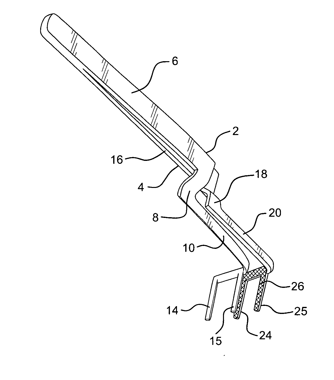
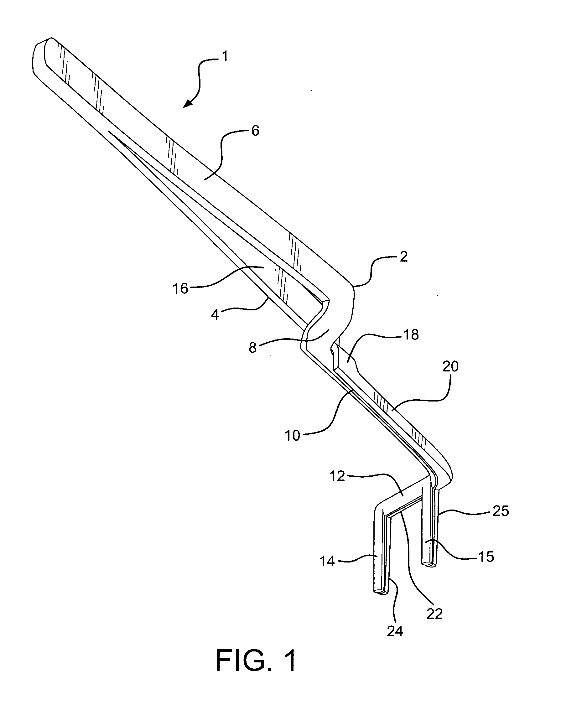
[0015]Dental articulating paper forceps 1 comprises opposed spring arms 2 and 4. Spring arm 2 comprises handle section 6, intermediate section 8 located substantially perpendicularly from the handle section, and clamp support section 10 which has right angled cantilevered member 12. Clamping support members 14 and 15 extend perpendicularly out from cantilevered member 12. Spring arm 4 comprises handle section 16, intermediate section 18 located substantially perpendicularly from the handle section, and clamp support section 20 which has right angled cantilevered member 22. Clamping support members 24 and 25 extend perpendicularly out from cantilevered member 22.

[0016]Spring arms 2 and 4 are joined together at their respective handle sections 6 and 16 via a tweezer-like configuration, such that they are resiliently spread apart at their upper ends. Spring arm 2 crosses over spring arm 4, such that intermediate sections 8 and 18 and sections 10 and 20 are biased together, such that se...


PUM


Abstract

Dental forceps for holding dental articulating paper has dual elongated spring arms, moveable toward and away from each other. The spring arms each have a lower handle section, an intermediate section extending from the lower handle section, and an upper section with a cantilevered member extending from the top end of the intermediate section. Clamping support arms extend outward from and perpendicular to the cantilevered member of each of the spring arms. The support arms have jagged surfaces which enhance the paper holding capability of the spring arms. When the spring arms are fully biased away from each other, the support arms are closed and articulating paper is held therebetween. When the lower handle sections of the spring arms are moved together, the support arms open to release the paper.

Description

BACKGROUND OF THE INVENTION[0001]The present invention is directed to forceps for firmly holding dental articulating paper which is to be positioned and then inserted between a patient's tooth and crown.[0002]There are a wide variety of articulating paper forceps which are employed by dentists to introduce articulating paper into a patient's mouth. One such common forcep utilizes a pair of spring arms which are interconnected to each other at one end and which have clamping elements at their distal ends. The arms are of different length and cross over at approximately their mid-sections. Clamp type members extend from the ends of the arms and are offset therefrom. The spring action of the arms maintains the clamp members in contact with one another. The contact is released to allow insertion of the articulating paper between the clamp members by forcing the ends of the arms together.[0003]However, this and similar configured forceps have inherent handicaps in that they are difficult...

Claims


Application Information

Patent Timeline
IPC IPC(8): A61C3/00
CPCA61C19/05A61C3/10
Inventor SOLANO, MILDREDAPALUCCI, RONALD A.
Owner SOLANO MILDRED
Learn More