
Aircraft tire and method of manufacture

a technology of pneumatic tires and airframes, applied in the field of pneumatic tires, can solve the problems of high degree of flexure in the crown area of pneumatic tires for high-speed applications, tire designs with zigzag belt layers cannot carry as heavy a load as required by current commercial aircraft design requirements,

Inactive Publication Date: 2011-06-23
THE GOODYEAR TIRE & RUBBER CO
View PDF46 Cites 14 Cited by
  • Summary
  • Abstract
  • Description
  • Claims
  • Application Information

AI Technical Summary

Problems solved by technology

Pneumatic tires for high speed applications experience a high degree of flexure in the crown area of the tire as the tire enters and leaves the contact patch.
This problem is particularly exacerbated on aircraft tires wherein the tires can reach speed of over 200 mph at takeoff and landing.
However, a tire designed with zigzag belt layers cannot carry as heavy a load as required by current commercial aircraft design requirements.
Further, there is generally a tradeoff between load capacity and weight.

Method used


Image

  • Aircraft tire and method of manufacture
  • Aircraft tire and method of manufacture
  • Aircraft tire and method of manufacture

Examples


first embodiment

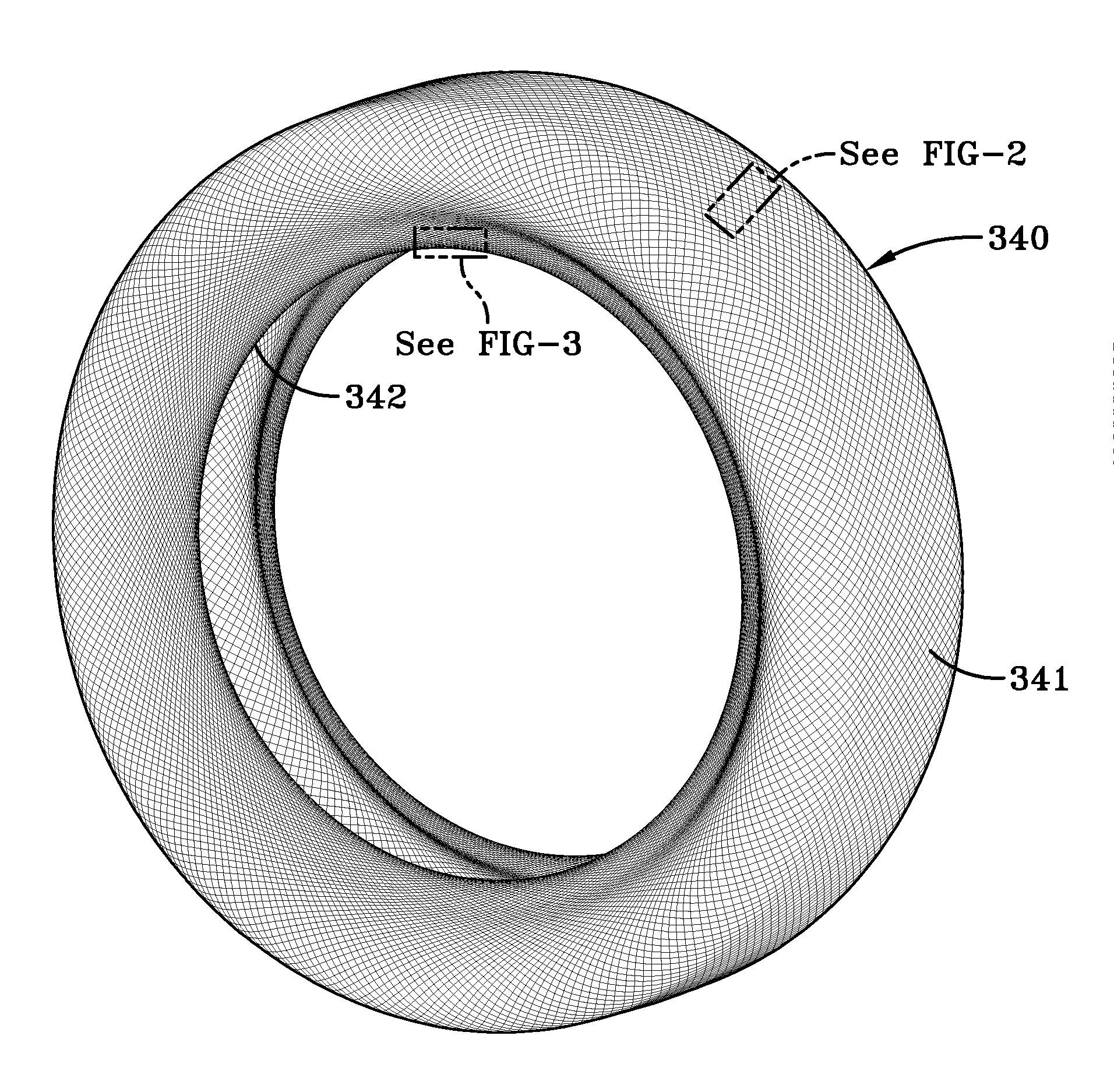
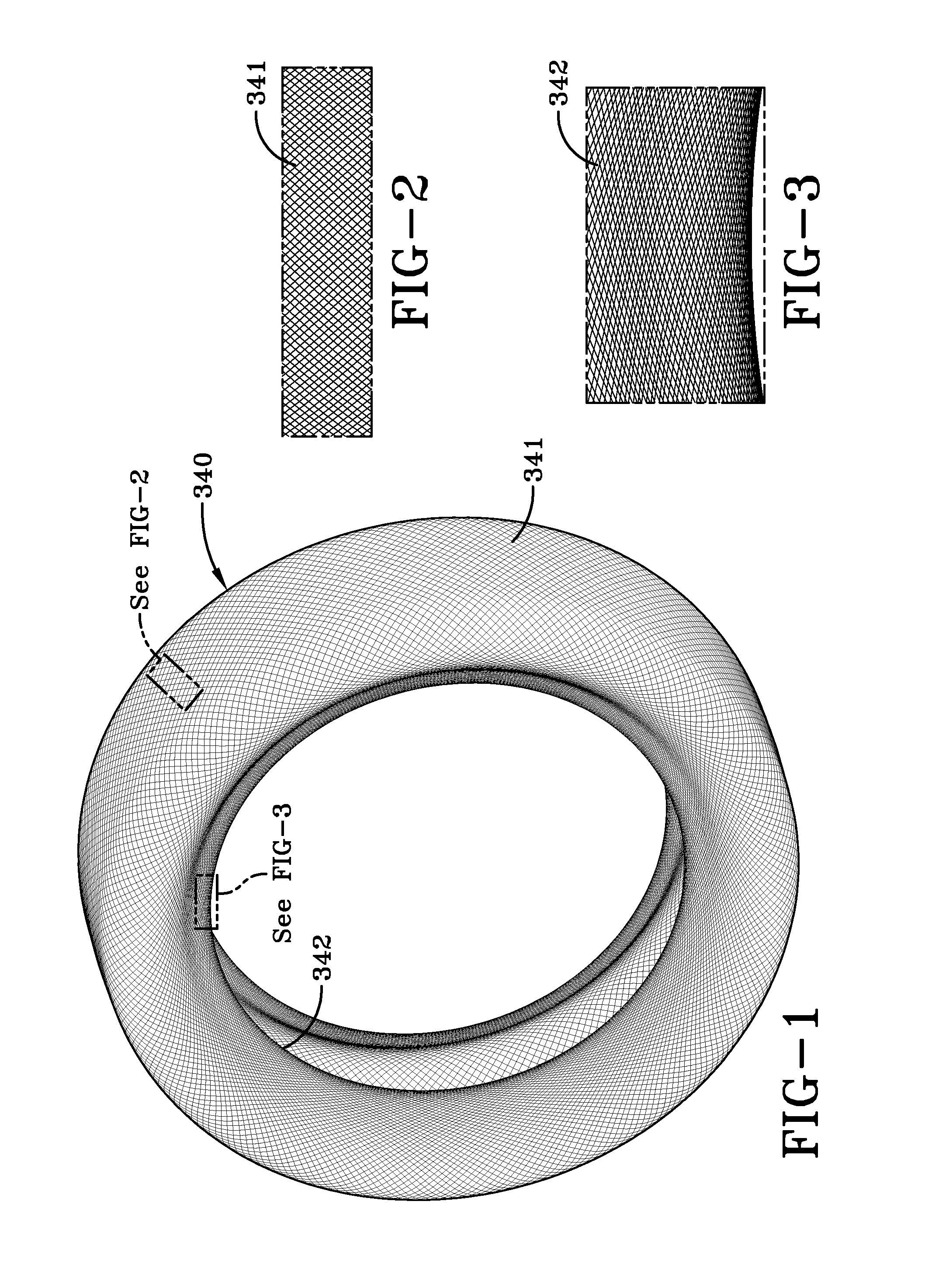
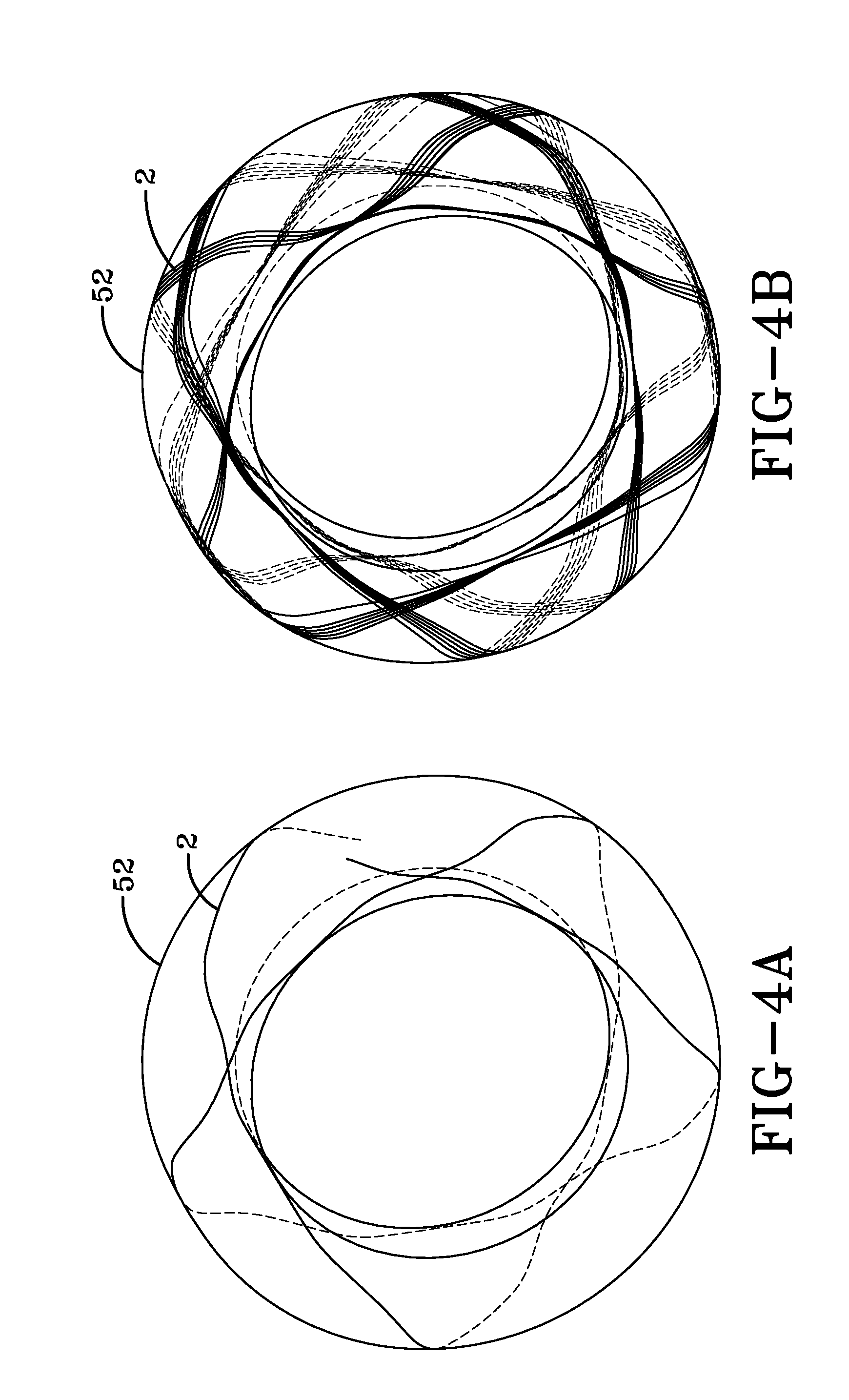
[0041]FIGS. 6-9 illustrate a green tire carcass of the present invention. The cords of the carcass are arranged in a geodesic orbital pattern wherein the cords are tangent to the bead radius of the tire. The close proximity of the cords results in a very large buildup of cord material in the bead area. In order to overcome this inherent disadvantage, the inventors modified the ply layup as described in more detail, below.

Apparatus

[0042]In a first embodiment of the invention, the tire 300 having a geodesic carcass is formed on a torus shaped core or tire blank 52. The core has an outer core surface which may be in the shape of a cylinder such as a tire building drum, a buffed carcass for a tire to be retreaded, and is preferably torus shaped to closely match the interior shape of the tire. The core is rotatably mounted about its axis of rotation and is shown in FIGS. 10 and 11. The core may be collapsible or formed in sections for ease of removal from the tire. The core may also cont...

second embodiment

[0049]an apparatus suitable for applying ply in a geodesic pattern onto a core is shown in FIG. 12. The apparatus includes a ply applier head 200 which is rotatably mounted about a Y axis. The ply applier head 200 can rotate about the Y axis + / −100 degrees. The rotation of the ply applier head 200 is necessary to apply the cord in the shoulder and bead area. The ply applier head 200 can thus rotate about rotatable core 52 on each side in order to place the ply in the sidewall and bead area. The ply applier head 200 is mounted to a support frame assembly which can translate in the X, Y and Z axis. The ply applier head has an outlet 202 for applying one or more cords 2. The cords may be in a strip form and comprise one or more rubber coated cords. Located adjacent the ply applier head 200 is a roller 210 which is pivotally mounted about an X axis so that the roller can freely swivel to follow the cord trajectory. The ply applier head and stitcher mechanism are precisely controlled by ...


PUM


Abstract

A pneumatic tire comprising a belt structure and a torus shaped carcass having a first inner radius and an outer radius, wherein the carcass is comprised of three or more layers of ply, wherein each layer of ply is formed from a rubberized strip of one or more cords, the strips being wound in an geodesic pattern having the cord extend across the carcass from a first shoulder to a second shoulder in a path that has at least one point tangent to the first inner radius located in the bead area of the tire.

Description

CROSS REFERENCE TO OTHER APPLICATIONS [0001]This application claims the benefit of and incorporates by reference U.S. Provisional Application No. 61 / 289,754 filed Dec. 23, 2009.FIELD OF THE INVENTION[0002]This invention relates to pneumatic tires having a carcass and a belt reinforcing structure, more particularly to high speed heavy load tires such as those used on aircraft.BACKGROUND OF THE INVENTION[0003]Pneumatic tires for high speed applications experience a high degree of flexure in the crown area of the tire as the tire enters and leaves the contact patch. This problem is particularly exacerbated on aircraft tires wherein the tires can reach speed of over 200 mph at takeoff and landing.[0004]When a tire spins at very high speeds, the crown area tends to grow in dimension due to the high angular accelerations and velocity, tending to pull the tread area radially outwardly. Counteracting these forces is the load of the vehicle which is only supported in the small area of the ti...

Claims


Application Information

Patent Timeline
IPC IPC(8): B60C9/07B60C9/18
CPCB60C9/023B60C15/05B60C2200/02B60C9/07B29D30/1635B60C9/20Y10T152/10765B60C15/0018B29D2030/082B60C2009/0491B60C2009/2035B60C2009/2025B60C2009/2032B29D30/16Y10T152/10783
Inventor LOSEY, ROBERT ALLENLANDERS, SAMUEL PATRICKGOBINATH, THULASIRAM
Owner THE GOODYEAR TIRE & RUBBER CO
Learn More