System and method for simplified activity based setup of a controlling device

Active Publication Date: 2011-06-09
UNIVERSAL ELECTRONICS INC
View PDF76 Cites 21 Cited by
  • Summary
  • Abstract
  • Description
  • Claims
  • Application Information

AI Technical Summary

Benefits of technology

[0003]In accordance with the teachings of this invention, a universal controlling device may be provisioned with keys for selecting designated activities such as “Watch TV,”“Watch as movie,” etc. In order to configure the controlling device for each of the activities, a simple series of keystrokes by a user may register those appliances which participate in that activity. Thereafter, upon selection of that activity key and entry of the controlling device into the corresponding activity mode, the controlling device may configure itself with a pre-programmed power macro sequence and a predetermined function key command mapping, both derived from the appliance registrations provided by the user. By way of example, if a user registers only a TV and a set top box for the activity “Watch TV,” then while that activity is selected the volume control

Problems solved by technology

While use of a universal controlling device to consolidate system control functionality into a single user interface is common in such systems, a recognized disadvantage of the basic form of such controlling devices is the requirement for a user to continually switch the controlling device operational mode back and forth between appliances to be controlled during set up and operation of the equipment.
However, all of these methods necessitate considerable user interaction to initially configure the controlling device to operate as desired, performed on the remote itself, on an associated programming device such as a personal computer, or some combination thereof.

Method used


Image

  • System and method for simplified activity based setup of a controlling device
  • System and method for simplified activity based setup of a controlling device
  • System and method for simplified activity based setup of a controlling device

Examples


Embodiment Construction

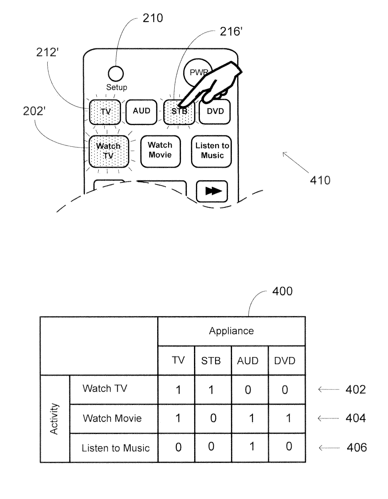
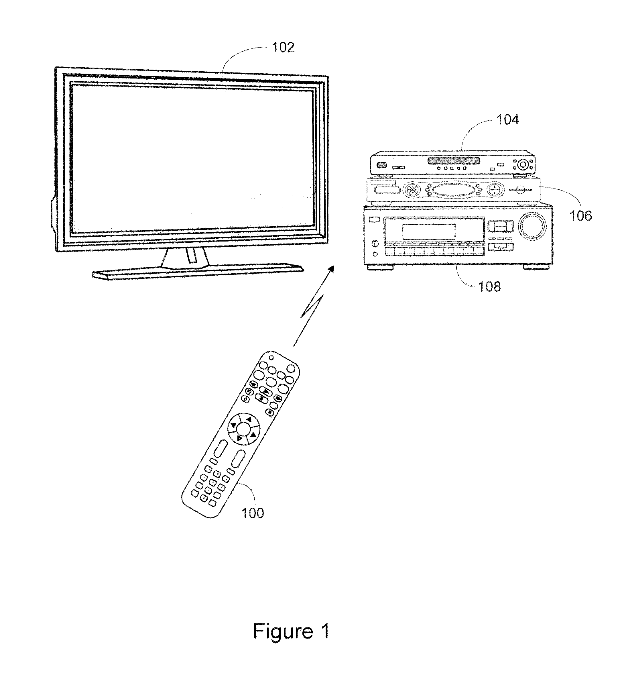
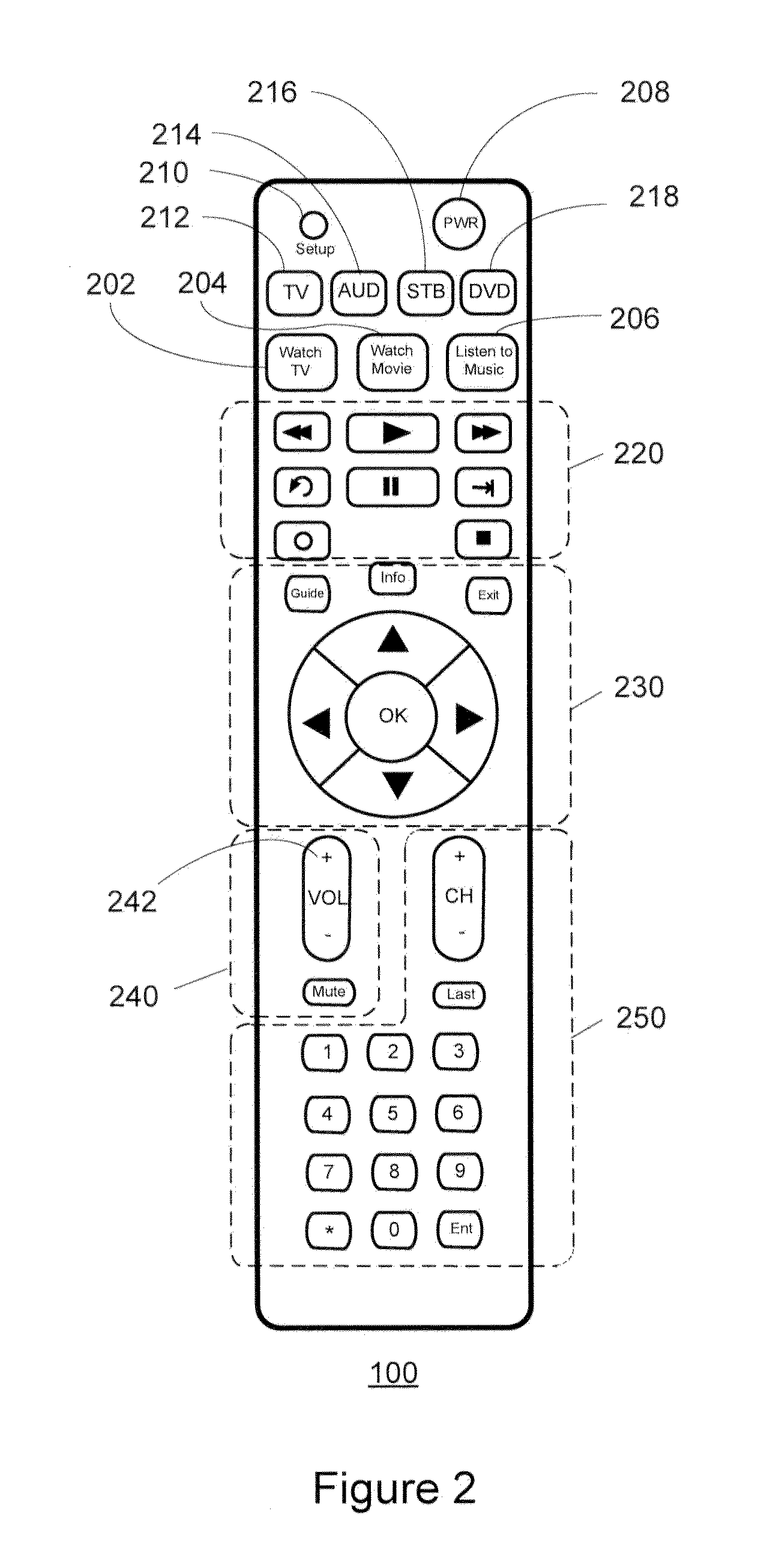
[0013]Turning now to FIG. 1, there is illustrated an exemplary system in which a controlling device 100 is configured to control various controllable appliances, such as a television 102, a DVD player 104, a set top box (“STB”) 106, and an AV receiver 108. As is known in the art, the controlling device 100 maybe capable of transmitting commands to the appliances, using any convenient IR, RF, Point-to-Point, or networked protocol, to cause the appliances to perform operational functions. While illustrated in the context of a television 102, DVD player 104, STB 106 and AV receiver 108, it is to be understood that controllable appliances may include, but need not be limited to, televisions, VCRs. DVRs, DVD players, cable or satellite converter set-top boxes (“STBs”), amplifiers, CD players, game consoles, home lighting, drapery, fans, HVAC systems, thermostats, personal computers, etc. In an illustrative embodiment controlling device 100 may be further adapted to permit a user to rapid...


PUM


Abstract

A controlling device having an activity mode corresponding to a controllable activity in which activation of a command key within a logical group of command keys of the controlling device causes a transmission of command data to control one or more functional operations of an intended target appliance. For a controllable activity the controlling device has a memory in which is stored a plurality of predetermined appliance to logical group of command keys mappings. To configure the controlling device for the controllable activity one or more predetermined keys of the controlling device are activated to thereby designate one or more intended target appliances for the controllable activity. When the controlling device is then placed into the activity mode corresponding to the controllable activity, the controlling device will use the configuration to select one of the plurality of predetermined appliance to logical group of command keys mappings to determine which appliance command data to transmit in response to an activation of a command key within a logical group of command keys.

Description

BACKGROUND[0001]This invention relates generally to controlling devices, such as for example universal remote controls, and more specifically to systems and methods for configuration of such controlling devices, by way of general example, to match such controlling devices to appliances to be controlled, to define favorite channels, etc., and to provide methods for a user to rapidly and conveniently program activity-based configuration parameters for use in such controlling devices.[0002]Today, even simple home entertainment systems may comprise multiple appliances such as for example a TV set, a cable and / or satellite box, an AV receiver, a DVD player, etc. While use of a universal controlling device to consolidate system control functionality into a single user interface is common in such systems, a recognized disadvantage of the basic form of such controlling devices is the requirement for a user to continually switch the controlling device operational mode back and forth between ...

Claims


Application Information

Patent Timeline
IPC IPC(8): G05B11/01
CPCG08C2201/92G08C17/02G08C19/00G09G5/00H03M11/00H04L17/02
Inventor KOHANEK, JEFFREYAMMARI, RAMZI
Owner UNIVERSAL ELECTRONICS INC
Why Eureka
Try Eureka