
Fiber Optic Terminals, Systems, and Methods for Network Service Management

a fiber optic terminal and fiber optic technology, applied in the field of fiber optic terminals and systems, can solve the problems of increasing the total cost, potentially disrupting the service to subscribers, and the initial cost of providing onus capable of supporting differentiated pon services may be initially higher

Inactive Publication Date: 2011-06-09
CORNING CABLE SYST LLC
View PDF9 Cites 17 Cited by
  • Summary
  • Abstract
  • Description
  • Claims
  • Application Information

AI Technical Summary

Benefits of technology

The patent describes a fiber optic network system that can provide different network services to subscribers using a single fiber optic terminal. This is achieved by connecting the subscriber to different optical paths in the fiber optic terminal, each carrying a different network service. This allows for more efficient use of the network, as each optical path can be used for multiple services. The system can also provide overlapping network services, and can be easily upgraded or reconfigured by changing the optical path connected to the subscriber. The technical effect of this system is that it provides greater flexibility and customization for network services, allowing for different services to be provided to different subscribers on the same network.

Problems solved by technology

However, this approach would also require eventually swapping-out initially installed ONUs with ONUs that support the differentiated PON services supported by the PON, thus increasing total cost and potentially disrupting service to subscribers.
However, initial costs of providing ONUs capable of supporting differentiated PON services may be initially higher than using the delay approach.

Method used


Image

  • Fiber Optic Terminals, Systems, and Methods for Network Service Management
  • Fiber Optic Terminals, Systems, and Methods for Network Service Management
  • Fiber Optic Terminals, Systems, and Methods for Network Service Management

Examples


Embodiment Construction

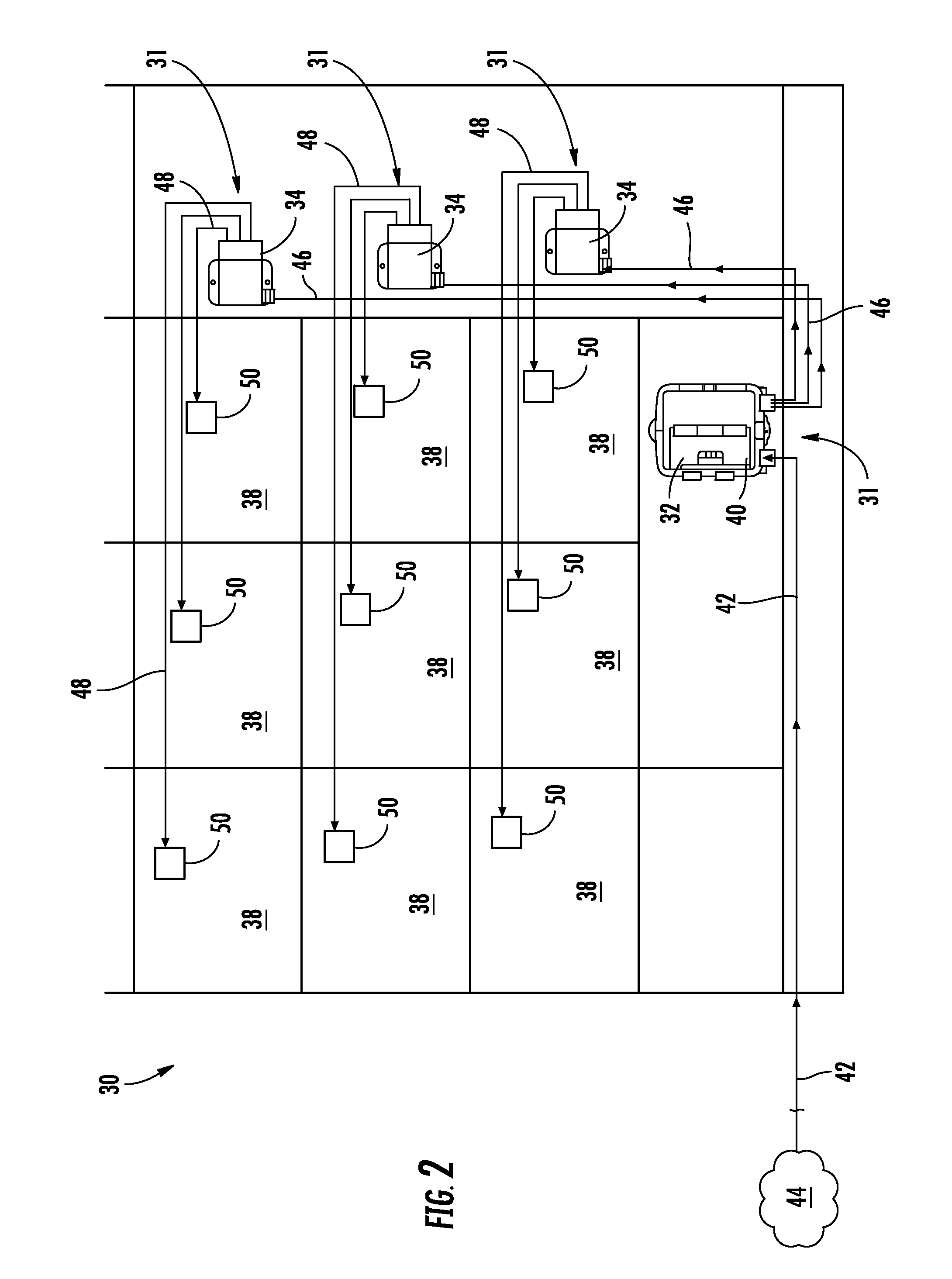
[0010]Embodiments disclosed in the detailed description include fiber optic terminals, systems, and methods for providing different (i.e., differentiated) network services to subscribers of a fiber optic network. A network service refers to a technology or platform used to carry or deliver an application, product, or service. In certain embodiments, fiber optic terminals, systems, and methods are disclosed for providing more than one network service over a fiber optic network to subscribers supported by the same fiber optic terminal. As a result, the optical paths in the fiber optic terminal do not have to be homogeneous wherein each optical path would carry the same optical signals and thus the same network services. Thus, differentiated levels and / or types of network services can be provided to different subscribers supported by the same fiber optic terminal. Further, by providing multiple optical paths in the fiber optic terminal, additional network services can be migrated to a ...


PUM


Abstract

Fiber optic terminals, systems, and methods for providing differentiated network services to subscribers of a fiber optic network are disclosed. In certain embodiments, fiber optic terminals and methods are disclosed for providing more than one network service to subscribers supported by the same fiber optic terminal. In one embodiment, a fiber optic terminal is provided comprising a first optical path connected to a first network-side optical fiber providing a first network service to a first subscriber-side optical fiber. The fiber optic terminal also comprises a second optical path connected to a second network-side optical fiber providing a second network service differentiated from the first network service to a second subscriber-side optical fiber. In this manner, differentiated network services can be provided to subscribers supported by the fiber optic terminal by configuring connections of the subscribers to either the first optical path or second optical path in the fiber optic terminal.

Description

BACKGROUND[0001]1. Field of the Disclosure[0002]The technology of the disclosure relates to fiber optic terminals, systems, and methods for providing differentiated network services and / or differentiated network service overlays to subscribers of a fiber optic network.[0003]2. Technical Background[0004]To provide improved performance to subscribers, communication and data networks are increasingly employing optical fiber. The benefits of optical fiber are well known and include higher signal-to-noise ratios and increased bandwidth. To further improve performance, fiber optic networks are increasingly providing optical fiber connectivity all the way to end subscribers. These initiatives include various fiber-to-the-premises (FTTP), fiber-to-the-home (FTTH), and other fiber initiatives (generally described as FTTx). In this regard, FIG. 1 illustrates an exemplary fiber optic network 10. The fiber optic network 10 in this example is a passive optical network (PON). A PON is a point-to-...

Claims


Application Information

Patent Timeline
Patent Type & Authority Applications(United States)
IPC IPC(8): H04J14/00
CPCH04J14/0227H04J14/0282H04J14/0286H04J14/0256H04Q11/0067H04Q2011/0079H04M1/003
Inventor CONNER, MARK E.DUNN, JR., KENNETH F.
Owner CORNING CABLE SYST LLC
Learn More