Transverse regulated flux machine
a technology of flux machine and rotor, which is applied in the direction of machines/engines, electric generator control, transportation and packaging, etc., can solve the problem that the prime mover, which generates the rotation of the rotor in the generator, often has a variable speed
- Summary
- Abstract
- Description
- Claims
- Application Information
AI Technical Summary
Benefits of technology
Problems solved by technology
Method used
Image
Examples
embodiment 200
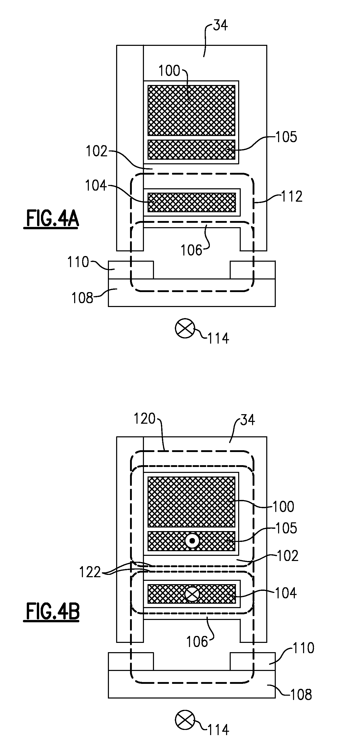
[0038]FIG. 5 shows a machine embodiment 200 which is single phase, and which is provided with two channels 204A and 204B, such that it is fault tolerant. The embodiment of FIG. 5 has an internal stator 202 surrounded by the rotor 206 and its permanent magnets 208. Otherwise, the machine operates much like the FIGS. 4A and 4B. In particular, the outer rotor / inner stator embodiments might be best integrated into a machine used in combination with a wheel, engine, propeller, pump, etc., wherein the inner stator may be more convenient.
embodiment 210
[0039]FIG. 6 shows another embodiment 210, wherein the rotor 212 is internal to the stator, and its channels 216A and 216B.
[0040]FIG. 7 shows a system with the dual single phase arrangement associated with the FIGS. 5 and 6 embodiments. As shown, the main windings 100 are provided by separate winding sets 234 and 236 associated with the branches A and B as shown in FIGS. 5 and 6. Further, independent permanent magnet sets 230 and 232 are associated with each of these redundant sets. A central controller 400 includes a load sharing algorithm for paralleling two dc power channels connected to the load. The controller 400 derives the voltage reference signals for each channel in response to the feedback signals from voltage sensor 408 and current sensor 410.
[0041]Rectifiers 401 provide power to H-bridges 402 that control current in each control coil 406 associated with the winding sets, 234, and 236 in response to the output of the current regulators 403. The voltage regulators 404 gen...
embodiment 320
[0043]FIG. 9 shows an embodiment 320 having an internal rotor 322, and the redundant three-phase pole pieces 325, 326, and 327 associated with its stator housing 324.
[0044]A control circuit 250 for the FIGS. 8 and 9 embodiment is illustrated in FIG. 10.
[0045]In FIG. 10, a control system for a three-phase generator arrangement is illustrated, and associated with the FIG. 8 and FIG. 9 embodiments. The main windings 100 are shown as two separate three-phase winding sets 354 and 356. A central controller 400 includes a load sharing algorithm for paralleling two dc power channels connected to the load. The controller 400 derives the voltage reference signals for each channel in response to the feedback signals from voltage sensor 408 and current sensor 410.
[0046]Rectifiers 401 provide power to H-bridges 402 that control current in each control coil 406 associated with the winding sets, 354, and 356 in response to the output of the current regulators 403. The voltage regulators 404 genera...
PUM
 Abstract
Description
Claims
Application Information
 - R&D
- Intellectual Property
- Life Sciences
- Materials
- Tech Scout
- Unparalleled Data Quality
- Higher Quality Content
- 60% Fewer Hallucinations
Browse by: Latest US Patents, China's latest patents, Technical Efficacy Thesaurus, Application Domain, Technology Topic, Popular Technical Reports.
© 2025 PatSnap. All rights reserved.Legal|Privacy policy|Modern Slavery Act Transparency Statement|Sitemap|About US| Contact US: help@patsnap.com


