
Electrically Operated Hair Cutting Device

a hair cutting device and electric technology, applied in the direction of metal working devices, etc., can solve the problems of limiting the comfort of the hair cutting device, and achieve the effects of improving the degree of freedom of movement of the contact surface, gentle shaving process, and better follow the surface of the skin

Inactive Publication Date: 2011-06-09
THE PROCTER & GAMBLE COMPANY
View PDF15 Cites 16 Cited by
  • Summary
  • Abstract
  • Description
  • Claims
  • Application Information

AI Technical Summary

Benefits of technology

[0006]This object is achieved by the present invention. Due to the fact that according to the present invention the shaving head frame is now mounted pivotably on the bearer element via a central bearing, and the bearing has play running in the upward and downward movement range of the shaving head frame, in addition to the uniform lowering of the cutting unit and thus also of the shaving head frame the frame can additionally be pivoted about the central bearing in the clockwise or counterclockwise direction, which makes possible an oblique positioning of the additional cutting device, and also makes it possible for this device to better follow the surface of the skin. This results in a more gentle shaving process, because the cutting device can lie uniformly against the skin without requiring great exertion in the users shaving movements. A slight rotation, in the clockwise or counterclockwise direction, of the cutting device is superposed on the uniform lowering of the cutting device, improving the degree of freedom of the movement of the contact surface of the cutting device. In this way, an even more gentle and more thorough shave is enabled according to the present invention.
[0007]In order to enable a pivoting movement that is rotatable about the central bearing within small limits, in addition to the upward and downward movement of the cutting device, according to one embodiment of the present invention, this bearing consists of a pin formed on the shaving head frame that engages in a groove formed on the bearer element. This groove is dimensioned long enough in the direction of the upward and downward movement of the shaving head frame that it permits the movement of the pin. Thus, the cutting device is laterally guided by the pin via the groove, and can nonetheless slide upward or downward along this groove. This makes possible a rotation of the cutting device about the pin, which in addition to the uniform lowering enables a further lowering of the left or right side of the cutting device in the clockwise or counterclockwise direction. Due to the groove-pin construction, the cutting device can be mounted on the bearer element particularly easily.
[0008]Another embodiment of the present invention provides that the oscillating movement can be transmitted to the cutting device in nearly frictionless fashion. Here, the pivoted lever, which is drivable by the drive motor, engages, via a coupling arrangement, in an access of the one cutting element, which moves back-and-forth, the coupling arrangement having means that permit both rotation and an upward and downward movement of the corresponding cutting element. In this way, the oscillating movement can also easily and economically be transmitted to the cutting element that moves back-and-forth, even during lowering or rotation. For this purpose, an embodiment of the present invention describes that the means are made up on the one hand of a fork-shaped claw, formed on the free end of the pivot lever, that engages in a shaft formed on the cutting element, such that in the initial position of the one cutting element there is a space between the free end of the claw and the end of the shaft. At the same time, the end surfaces of the claw, which are in sliding contact with the walls of the shaft, are curved outward. Through this measure, the rotation of the one cutting element on the pivot lever is compensated. At the same time, the oscillating movement can be transferred to the one cutting element almost without play and with low friction.

Problems solved by technology

The combs of the two front cutting devices can be moved only laterally back and forth relative to each other in the bearer part, so that it is not the case that the entire comb front can follow an uneven skin surface, which limits the comfort of the hair cutting device.

Method used


Image

  • Electrically Operated Hair Cutting Device
  • Electrically Operated Hair Cutting Device
  • Electrically Operated Hair Cutting Device

Examples


Embodiment Construction

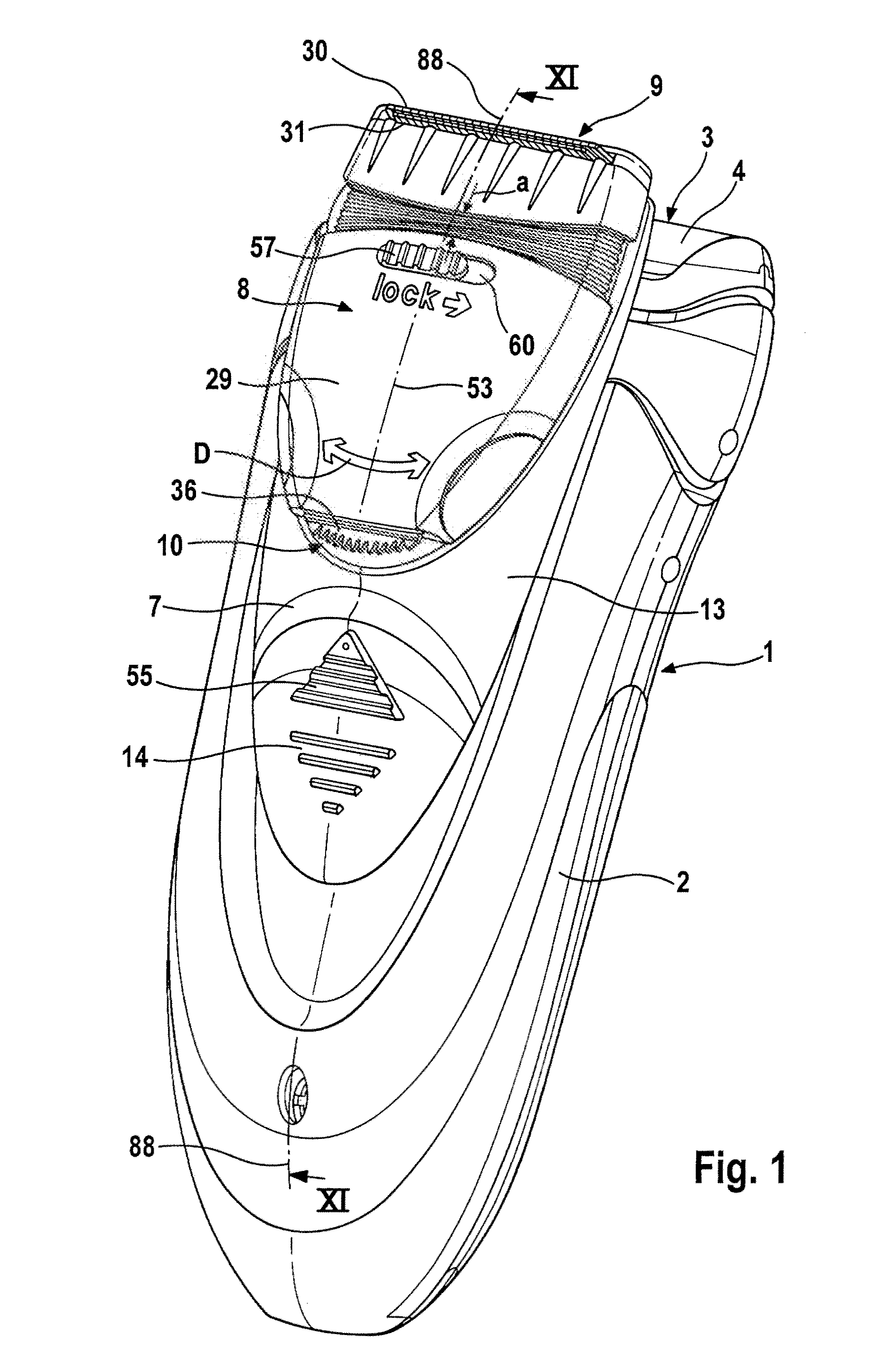
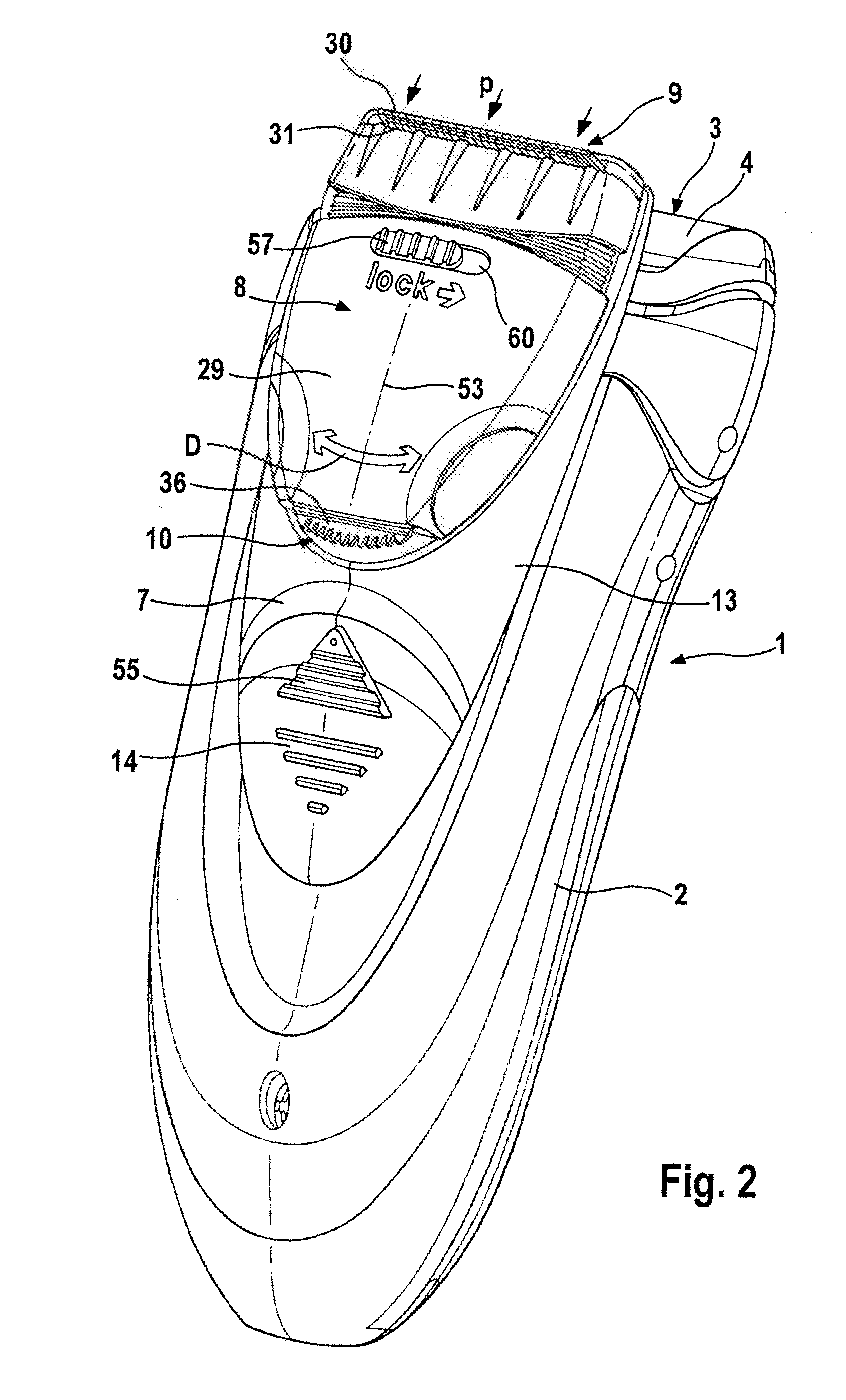
[0028]The perspective view according to FIGS. 1 through 3 shows a known hair cu device 1, fashioned as an electric shaver, having a housing 2 and a short hair cutting system 3. Short hair cutting system 3 is made up of an upper blade 4, fashioned as a shaving foil, under which, according to FIG. 11, a lower blade 48 is moved back and forth in oscillating fashion via a drive pin 49. Via an eccentric coupling 51, drive pin 49 is mechanically engaged with an eccentric pin 32. Eccentric pin 32 is mounted in rotationally fixed fashion on a drive shaft 52 of a drive motor 47. Housing 2 accommodates drive motor 47 required for this, as well as, if warranted, electrical storage cells 46, and / or a power and charging part 50 for supplying energy to drive motor 47.

[0029]According to FIG. 11, an on / off switch 5 is situated on the rear side of housing 2. This switch switches the supply of energy to drive motor 47, which in the switched-on state according to FIG. 11 drives lower blade 48 of short...


PUM


Abstract

The present invention relates to an electrically operated hair cutting device having a short hair cutting system fashioned on a front end of a housing and having a bearer part, attached to the front or rear side of the housing, that accepts at least one additional cutting device. The cutting device is made up of at least two cutting elements that slide relative to one another via a drive motor, the cutting elements of the additional cutting device being fashioned in a shaving head frame. The shaving head frame, with the cutting elements, is mounted in the bearer part against the force of a spring system. In addition, the shaving head frame is guided upward and downward in the bearer part via guide elements. According to the present invention, the shaving head frame is pivotably mounted on the bearer part via a central bearing. In this way, a shave is ensured that is particularly gentle to the skin.

Description

FIELD OF THE INVENTION[0001]The present invention relates to an electrical hair cutting device.BACKGROUND OF THE INVENTION[0002]EP 1 641 601 B1 discloses a hair cutting device in which a bearer element is attached to the front side of the razor housing, on which element there is situated, diametrally opposite, a respective cutting device formed as a long hair trimmer that is driven in simultaneously oscillating fashion after switching on and displacement of the sliding switch. Together with the cutting device, the bearer element can be pivoted about an axis of rotation, so that in the one position the cutting device can be used with the long cutting combs and in the other position the cutting device can be used with the shorter cutting combs. If the sliding switch is brought for example into position 1, shaving can take place with the short hair cutting system.[0003]If the sliding switch is brought into position 2, one of the two upward-directed cutting devices moves far enough out ...

Claims


Application Information

Patent Timeline
IPC IPC(8): B26B19/04
CPCB26B19/063B26B19/102B26B19/105
Inventor ERNDT, ANDREASDIETZEL, DANIELPIESKER, THORSTENSTIMPEL, JOHANNESSALOMEZ, NICOLASLUDAESCHER, UWEMATERN, MATTHIAS
Owner THE PROCTER & GAMBLE COMPANY
Learn More