
Multijoint cable protection and guide device

a cable protection and multi-joint technology, applied in the direction of mechanical equipment, other domestic objects, machine supports, etc., can solve the problems of theft appearance becoming formless, damaged cables, etc., and achieve the effect of reducing the burden of managing parts, smooth cable guide, and convenient work

Active Publication Date: 2011-05-26
HITACHI METALS LTD +1
View PDF3 Cites 27 Cited by
  • Summary
  • Abstract
  • Description
  • Claims
  • Application Information

AI Technical Summary

Benefits of technology

[0022]The multijoint cable protection and guide device of the invention is composed of the flexible belt member in which the plurality of center tubular portions through which cables and the like are respectively inserted and the pair of right and left side tubular portions disposed in parallel adjacent the center tubular portions are integrally molded. The device is also composed of the pair of right and left multijoint supporting members respectively inserted through the side tubular portions of the flexible belt member. Accordingly, the multijoint cable protection and guide device can guide the cables and the like protected within the center tubular portions while assuming the straight and flexed postures of the multijoint supporting members and has the following peculiar advantageous effects.
[0023]A first advantageous effect obtained by the multijoint supporting member composed of the large number of block bodies that are flexibly connected with each other is the avoidance of injection molding the pieces one by one with respect to a stainless steel member or a leaf spring as is done in the prior art. Accordingly, it is easy to cut and connect the multijoint supporting member. Comparatively, the prior art flexible member, composed of a supporting member, such as a stainless steel material, is difficult to cut and connect to steadily protect and guide cables that assume flexed and straight postures. Because the large numbers of block bodies are flexibly connected together by concave-convex snap-fitting, it remarkably reduces the burden of managing parts. Comparatively, in the prior art, various long and short supporting members are required, thus requiring more parts and more work to manage a larger number of parts.
[0024]A second advantageous effect is that the multijoint supporting member smoothly shifts from straight posture to flexed posture and vice versa. This is because the block bodies are flexibly connected by the concave-convex snap-fitting. The connecting pins provided in the front side portion of the block bodies interengage the connecting pin holes provided in the rear side portions of a preceding block body. The connecting pins of the succeeding block body are rotatably and axially supported by the connecting pin holes of the preceding block body. Accordingly, it becomes possible to smoothly guide the cables and the like by use of the invention,
[0025]A third advantageous effect is the ability to cut and connect the multi-joint member corresponding to its usage. The block body is concavely provided with tapered cutaway fitting portions. The tapered cutaway fitting portions extend continuously from the connecting pin holes in the rear side regions / portions to the rear side surface and enable the concave-convex fitting of the connecting pins in the front side regions / portion with the connecting pin holes in the rear side regions / portion. The connecting pins of a succeeding block body are attached to the connecting pin holes through the tapered cutaway fitting portions of the preceding block body without requiring an excessive fitting force in connecting the block bodies of the multijoint supporting member together.
[0026]A fourth advantageous effect is the protection and guidance of the cables and the like that assume flexed and straight postures even if the device is installed in a space close to an obstacle. Each block body is provided with the straight posture holding planes for keeping the block bodies in a straight state. Each block body is also provided with the flexed posture holding planes / surfaces for holding the block bodies in a flexed state. As a result, the straight posture holding planes and the flexed posture holding planes butt respectively with each other and position to hold the straight and flexed postures required for the multijoint supporting member.
[0027]A fifth advantageous effect is that because the flexible belt member is molded from synthetic resin material, it becomes easy to work and mold configurations of the plurality of center tubular portions and the pair of right and left side tubular portions that compose the light-weight flexible belt member corresponds to the shape of the cables and the like. Because the synthetic resin material of the flexible belt member has self-lubricating nature, it reduces sliding abrasion that is otherwise prone to be caused between the flexible belt member and the cables.

Problems solved by technology

The cables then become damaged and theft appearance becomes formless.

Method used


Image

  • Multijoint cable protection and guide device
  • Multijoint cable protection and guide device
  • Multijoint cable protection and guide device

Examples


embodiment

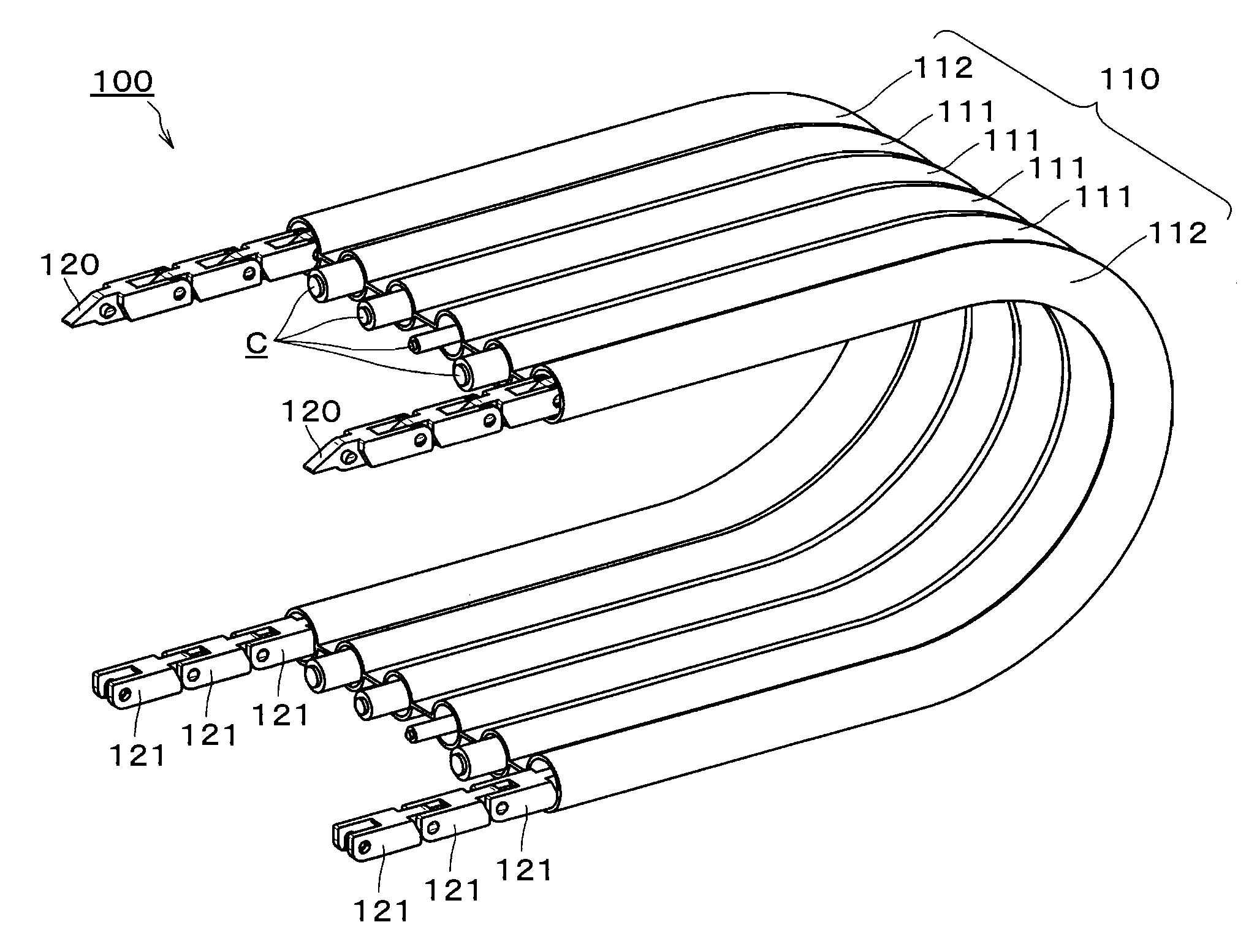
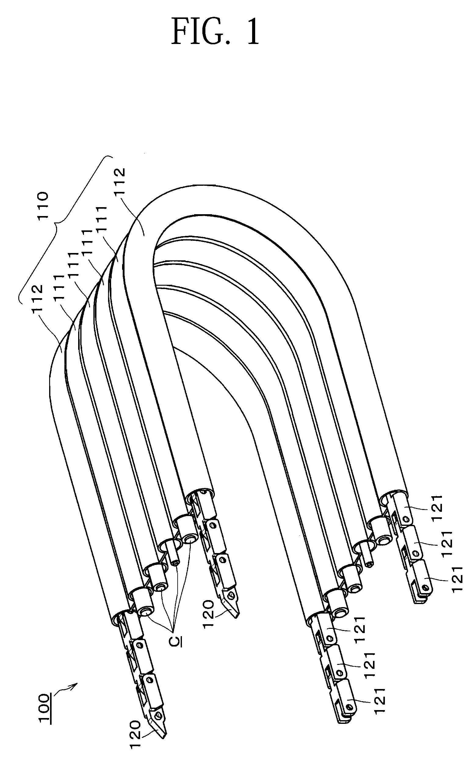
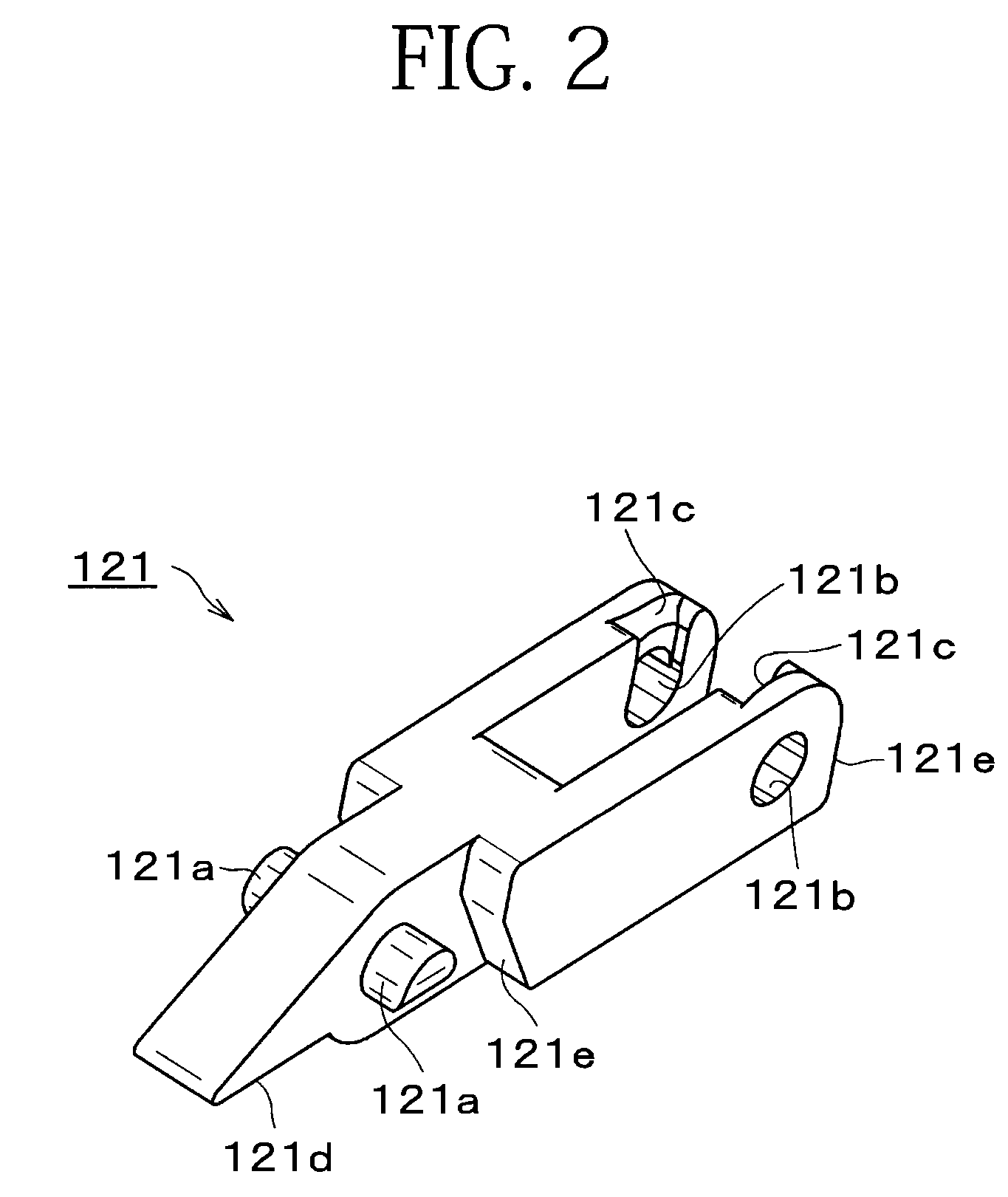
[0048]An embodiment of a multijoint cable protection and guide device of the invention will be explained with reference to the drawings. FIG. 1 shows an outline of one embodiment of the multijoint cable protection and guide device of the invention. FIG. 2 is a perspective view of a block body, shown in FIG. 1, and seen from the obliquely front upper side thereof. FIG. 3 is a perspective view of the block body shown in FIG. 1 seen from the obliquely rear upper side thereof. FIG. 4 is an assembly exploded view of a multijoint supporting member shown in FIG. 1. FIG. 5 illustrates a flexed state of the multijoint supporting member shown in FIG. 1. FIG. 6 is a side view of the multijoint supporting member showing a straight state thereof. FIG. 7 is a partially sectional side view of the multijoint supporting member showing a flexed state thereof.

[0049]One embodiment of the multijoint cable protection and guide device (100) of the invention is used for working machines, electronic devices...


PUM


Abstract

The invention provides a multijoint cable protection and guide device that steadily protects and guides cables and the like that assume flexed and straight postures. The device includes a flexible belt member in which a plurality of center tubular portions through which cables are inserted and a pair of right and left side tubular portions disposed in parallel along the center tubular portions. The center tubular portions and the pair of right and left side tubular portions are integrally molded. A pair of right and left multijoint supporting members is inserted through side tubular portions of the flexible belt member. The multijoint supporting member is composed of a large number of block bodies that are flexibly connected together by concave-convex fittings.

Description

CROSS REFERENCE TO RELATED APPLICATIONS[0001]This application claims the foreign priority benefit under Title 35, United States Code, §119(a)-(d) of Japanese Patent Application No. 2009-269012, filed on Nov. 26, 2009 in the Japan Patent Office, the disclosure of which is herein incorporated by reference in its entirety.BACKGROUND OF THE INVENTION[0002]1. Field of the Invention[0003]The present invention relates to a cable protection and guide device used for working machines, electronic devices, industrial robots, transportation equipment and the like. The invention is used to protect and guide flexible cables and hoses such as electrical cables, optical fiber cables, and fluid supplying hoses for feeding electricity, fluid, and air to such mobile machine or to a mobile section of the machine.[0004]2. Related Art[0005]When the cables are connected to a mobile object of a working machine, a civil-engineering machine, or a conveying device, the cables are twisted or tensioned unnatura...

Claims


Application Information

Patent Timeline
IPC IPC(8): F16L3/015F16L3/00
CPCF16G13/16H02G11/006F16G13/20H02G3/0487
Inventor TATSUTA, KIYOTAKEIKEDA, MASAAKIKOMIYA, SHOICHIROMATSUDA, TAKAYUKI
Owner HITACHI METALS LTD
Learn More