
Machine-plate mounting device for printer, and printer

a technology for mounting devices and printers, which is applied in printing plates, printing presses, printing, etc., can solve problems such as troublesome mounting of machine plates within printers, difficulty in accurately attaching machine plates, and difficulty in detaching and attaching machine-plate cylinders from and to machine-plate drive shafts

Active Publication Date: 2011-05-26
IZUME MASAYUKI
View PDF9 Cites 9 Cited by
  • Summary
  • Abstract
  • Description
  • Claims
  • Application Information

AI Technical Summary

Benefits of technology

[0030]According to the machine-plate mounting device for a printer of the present invention, and the printer of the present invention, as mentioned above, a cylindrical machine plate can be attached to and detached from the printer very easily.

Problems solved by technology

In such a case, mounting the machine plate within the printer is troublesome, and difficulty is encountered in accurately attaching the machine plate to the machine-plate cylinder.
In this case, since the machine-plate cylinder is considerably heavy, difficulty is encountered in detaching and attaching the machine-plate cylinder from and to the machine-plate drive shaft.

Method used


Image

  • Machine-plate mounting device for printer, and printer
  • Machine-plate mounting device for printer, and printer
  • Machine-plate mounting device for printer, and printer

Examples


Embodiment Construction

[0057]An embodiment of the present invention will next be described with reference to the drawings.

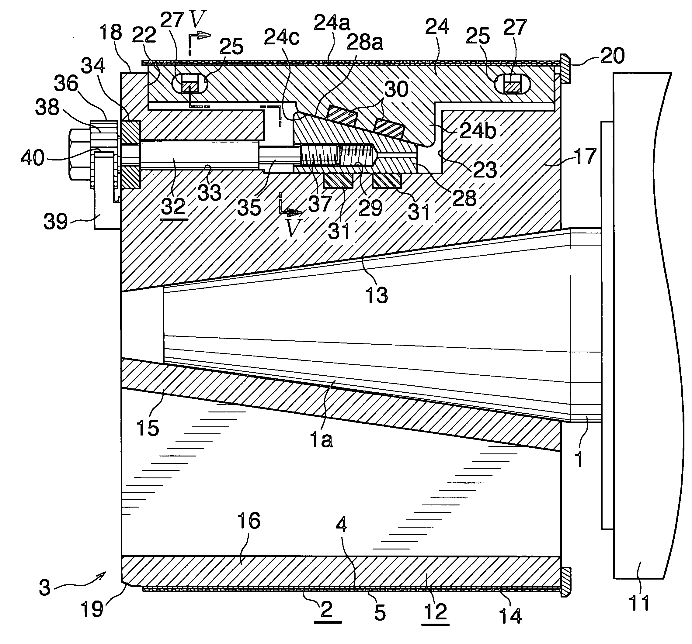
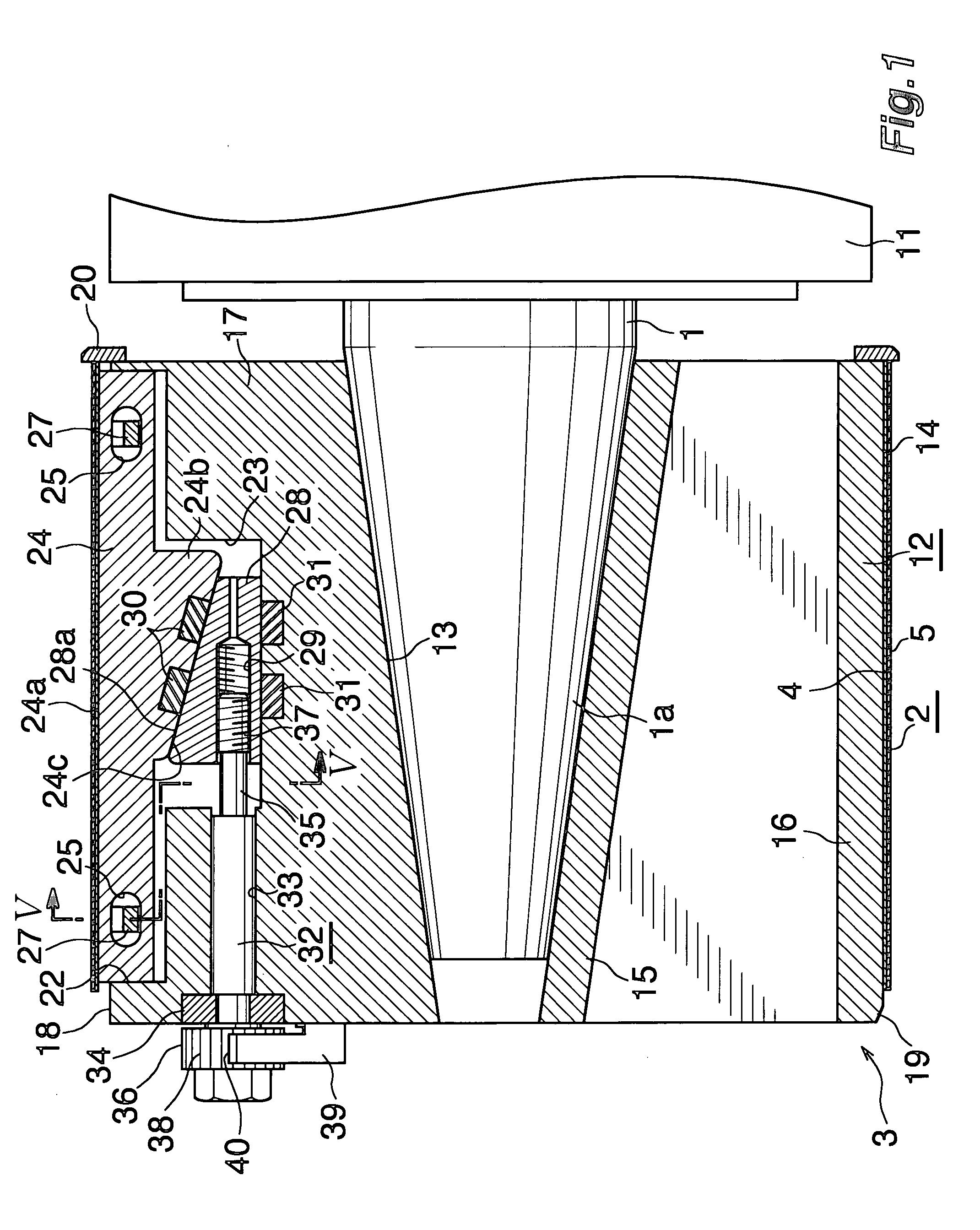
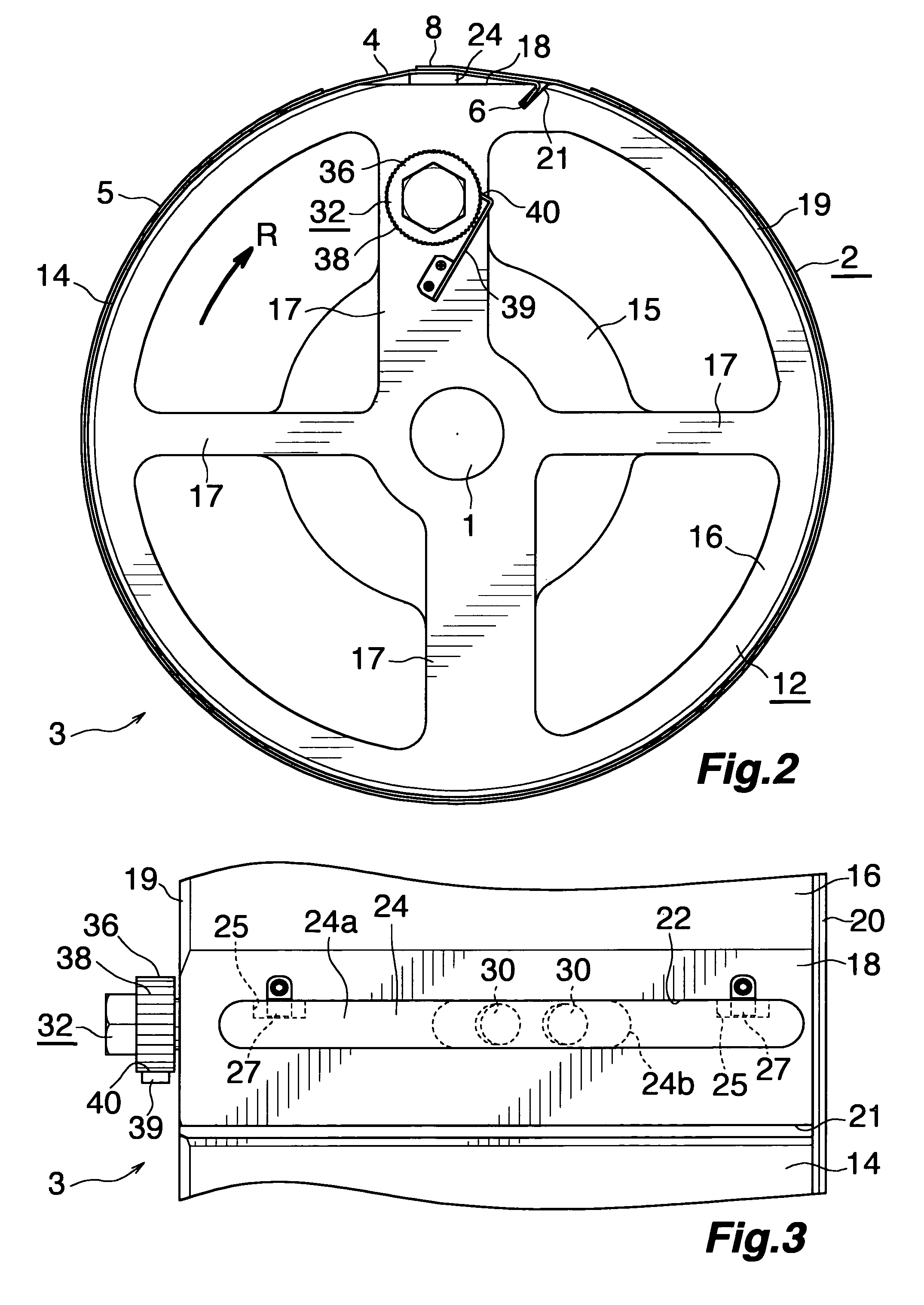
[0058]FIG. 1 is a vertical sectional view of a machine-plate mounting device 3 which is attached to a machine-plate drive shaft 1 of a printer and on which a machine plate 2 is mounted. FIG. 2 is a front view of the machine-plate mounting device 3 of FIG. 1. FIG. 3 is a plan view showing a portion of the machine-plate mounting device 3. FIG. 4 is a vertical sectional view showing, on an enlarged scale, a portion of the machine-plate mounting device 3 and a portion of the machine plate 2 as viewed before the machine plate 2 is mounted on the machine-plate mounting device 3. FIG. 5 is a sectional view (cross-sectional view) taken along line V-V of FIG. 1. FIG. 6 is a pair of perspective views showing the machine plate 2 and a machine-plate manufacturing step. FIG. 7 is a side view showing, on an enlarged scale, a portion of a sheet as viewed before formation of the machine plate of FIG. ...


PUM


Abstract

The present invention provides a machine-plate mounting device for a printer which can attach a cylindrical machine plate to the printer more easily and accurately. A machine-plate mounting device 3 is fixedly provided on a machine-plate drive shaft 1 of the printer for mounting a machine plate 2 having a forme area 5 provided on a portion of an outer circumferential surface of a machine plate body 4 formed from an elastic material into a cylindrical shape and an engagement portion 6 projecting radially inward from an inner circumference of the machine plate body 5 and extending in an axial direction. The machine-plate mounting device 3 includes a machine-plate cylinder section 12 fixedly provided on the machine-plate drive shaft 1 and having, on its outer circumference, a cylindrical machine-plate mounting surface 14 on which the machine plate 2 is mounted from a front-end side of the machine-plate drive shaft 1. The machine-plate mounting device 3 is configured such that the machine-plate cylinder section 12 has, on its outer circumference, a groove 21 for circumferential positioning into which the engagement portion 6 of the machine plate 2 is fitted from the front-end side of the machine-plate drive shaft 1, a stopper 20 for axial positioning with which an end portion of the machine plate 2 comes into contact, and a machine-plate fixation member 24 which presses a portion, other than the forme area 5, of the machine plate 2 mounted on the machine-plate cylinder section 12 from a radial inside direction toward a radial outside direction so as to bring the machine plate 2 into fixed-close contact with the machine-plate mounting surface 14 of the machine-plate cylinder section 12.

Description

TECHNICAL FIELD[0001]The present invention relates to a machine-plate mounting device for a printer and to a printer.BACKGROUND ART[0002]There is known a printer in which a machine plate is mounted on the outer circumference of a machine plate cylinder fixed on a machine-plate drive shaft.SUMMARY OF THE INVENTIONProblems To Be Solved By the Invention [0003]In the above-mentioned printer, a sheet-like machine plate may be wound onto a machine-plate cylinder fixed on a machine-plate drive shaft. In such a case, mounting the machine plate within the printer is troublesome, and difficulty is encountered in accurately attaching the machine plate to the machine-plate cylinder.[0004]In order to avoid such difficulty, the sheet-like machine plate may be wound onto the machine-plate cylinder while the machine-plate cylinder is detached from the machine-plate drive shaft, followed by fixation of the machine-plate cylinder on the machine-plate drive shaft. In this case, since the machine-plate...

Claims


Application Information

Patent Timeline
IPC IPC(8): B41F27/00
CPCB41P2227/21B41F27/105B41F27/06B41F27/10
Inventor IZUME, MASAYUKI
Owner IZUME MASAYUKI
Learn More