
Encoding module, associated encoding element, connector, printer-encoder and access control system

a technology of encoding module and associated encoding element, applied in the field of encoding module, can solve problems such as communication errors and collisions

Active Publication Date: 2011-05-19
ZEBRA TECH CORP
View PDF22 Cites 28 Cited by
  • Summary
  • Abstract
  • Description
  • Claims
  • Application Information

AI Technical Summary

Benefits of technology

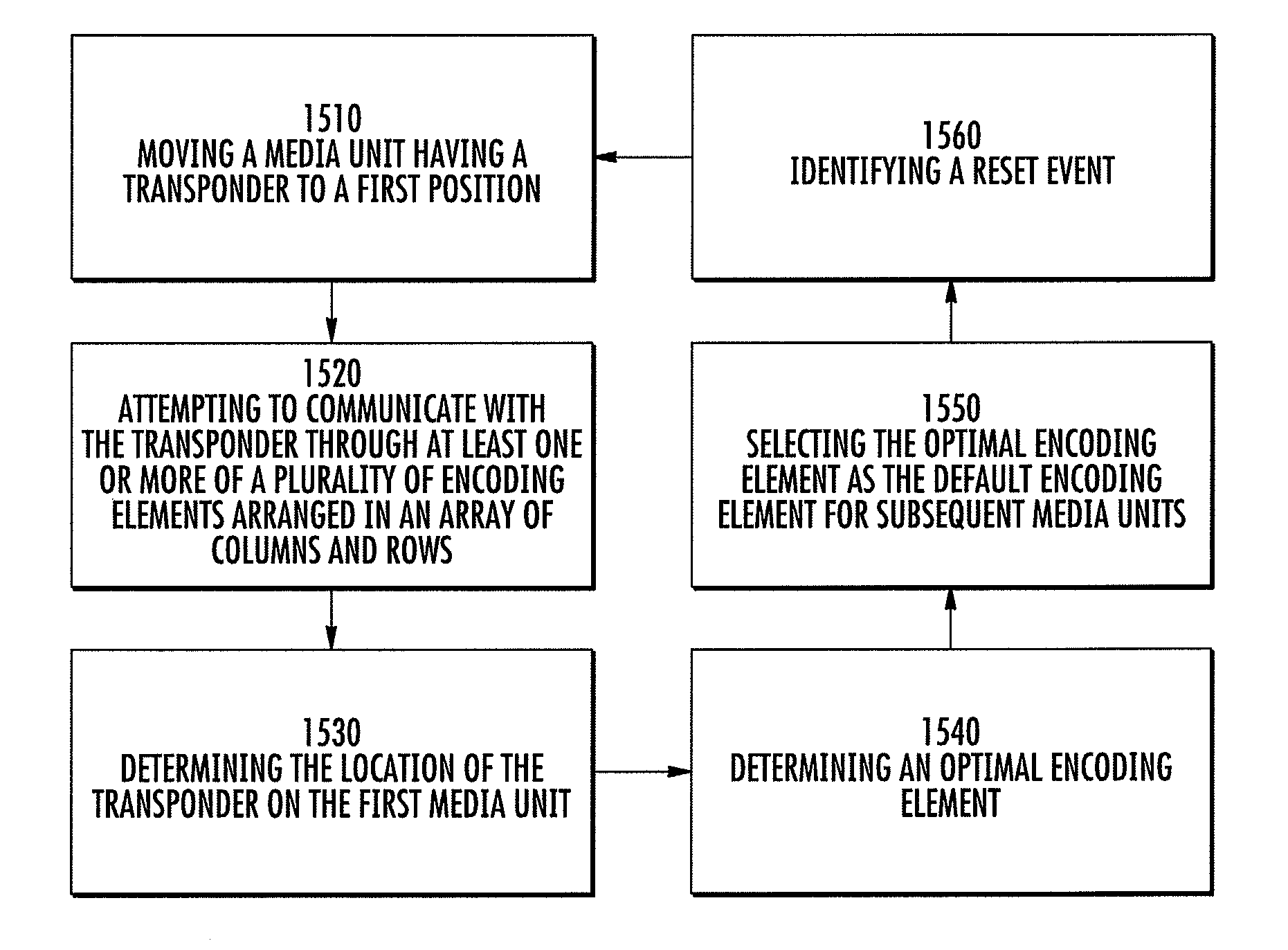
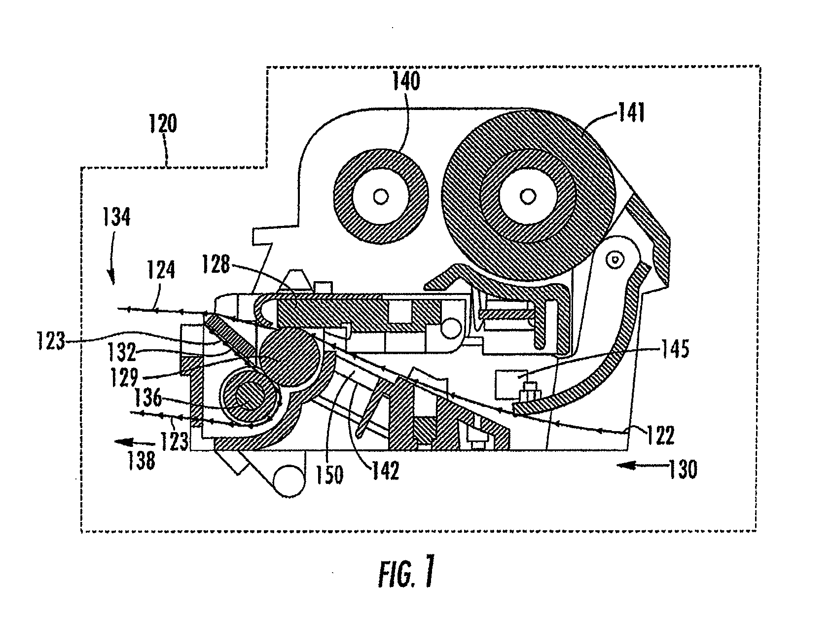
[0007]Embodiments include systems, methods, computer readable media, and other means for providing an encoding module, associated encoding element, connector, printer-encoder, and access control system. For example, embodiments can include RFID printer-encoders and be capable of encoding and / or printing one or more transponders (individually or simultaneously) that are embedded in one or more labels. When encoding / printing a number of transponders in close proximity to each other, embodiments discussed herein can be configured to target a particular transponder. Moreover, embodiments can conserve, among other things, space, cost, and weight normally associated with encoding devices, which have utilized other types of EMF collision management techniques or shielding components for alleviating unintentional multiple transponder activation. Embodiments of the present invention can be configured to encode a much broader range of tag types and meet the encoding pitch, as well as allow for transponder placement independence.

Problems solved by technology

Problems can occur when interrogating one targeted transponder surrounded by multiple adjacent transponders regardless on whether the transponders are field activated or independently powered by an internal energy source.
This simultaneous activation of multiple transponders may lead to collision or communication errors because each of the multiple transponders may transmit reply signals to the reader at the same time.

Method used


Image

  • Encoding module, associated encoding element, connector, printer-encoder and access control system
  • Encoding module, associated encoding element, connector, printer-encoder and access control system
  • Encoding module, associated encoding element, connector, printer-encoder and access control system

Examples


Embodiment Construction

[0007]Embodiments include systems, methods, computer readable media, and other means for providing an encoding module, associated encoding element, connector, printer-encoder, and access control system. For example, embodiments can include RFID printer-encoders and be capable of encoding and / or printing one or more transponders (individually or simultaneously) that are embedded in one or more labels. When encoding / printing a number of transponders in close proximity to each other, embodiments discussed herein can be configured to target a particular transponder. Moreover, embodiments can conserve, among other things, space, cost, and weight normally associated with encoding devices, which have utilized other types of EMF collision management techniques or shielding components for alleviating unintentional multiple transponder activation. Embodiments of the present invention can be configured to encode a much broader range of tag types and meet the encoding pitch, as well as allow fo...


PUM


Abstract

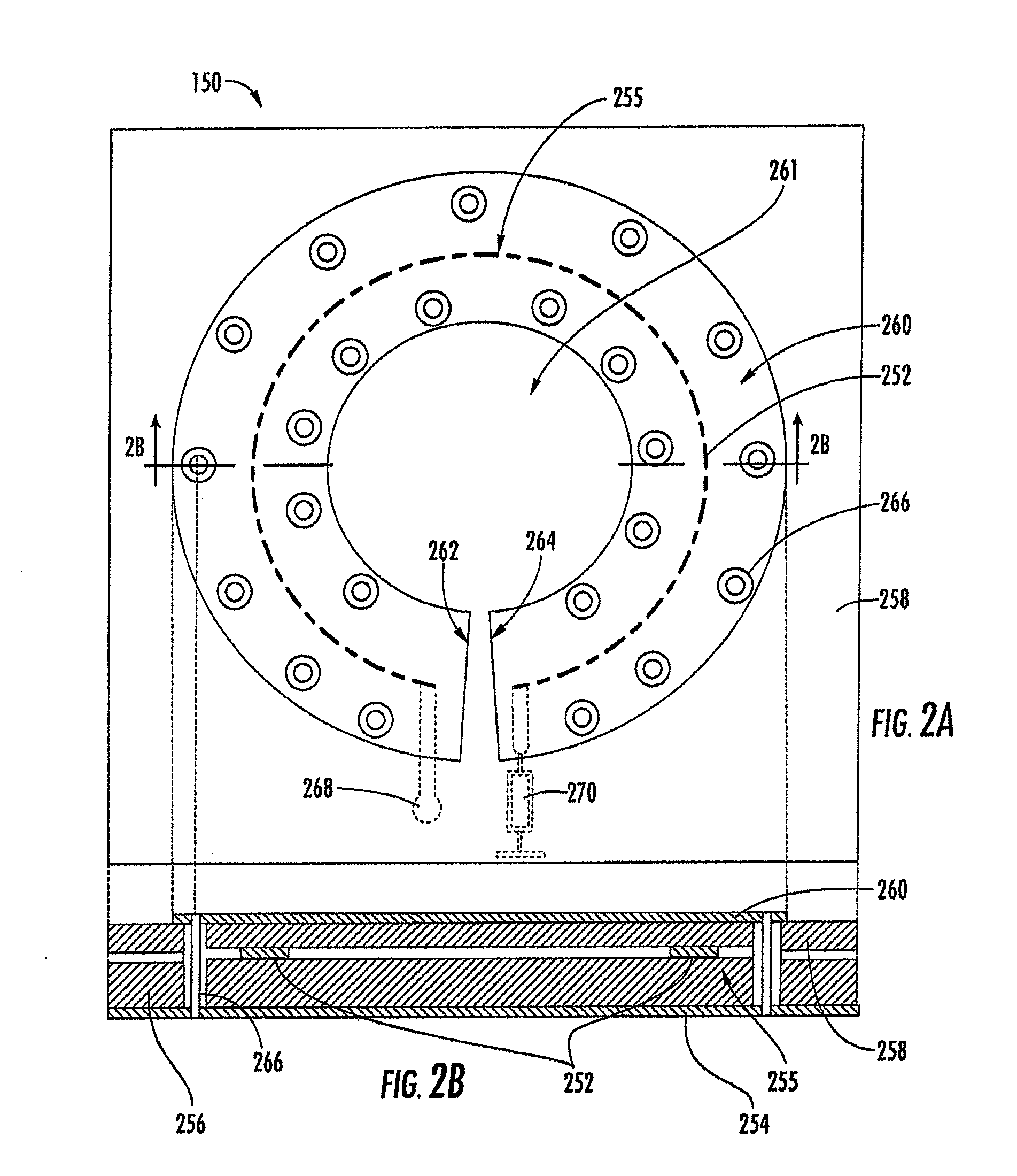
An encoding module and related systems and components are provided. The encoding module includes a plurality of encoding elements arranged in an array of columns and rows and one or more switching elements configured to selectively connect the encoding elements to a reader. The connection of the encoding elements may be based on the location of a targeted transponder disposed among multiple adjacent transponders to ensure the selective communication with the targeted transponder only. The module is configured for various types and locations transponders to be used within a system, such as a printer-encoder. Each encoding element may include a loaded conductive strip comprising a loop shape portion and a shield that corresponds to the loop shape portion. In another embodiment, an access control system having an encoding module with the plurality of couplers and an access card having a plurality of transponders corresponding to the couplers is provided.

Description

BACKGROUND[0001]1. Field of the Invention[0002]The present invention relates to an encoding module and related systems and components such as encoding elements, RFID printer-encoders, and access control systems.[0003]2. Description of Related Art[0004]Radio frequency identification (“RFID”) transponders, either active (e.g., battery-powered, -assisted, or -supported) or passive (e.g., RF field activated), are typically used with an RFID reader or similar device for communicating information back and forth. In order to communicate, an antenna of the reader exposes the transponder to a radio frequency (RF) electromagnetic field or signal. In the case of a passive UHF transponder, the RF electromagnetic field energizes the transponder and thereby enables the transponder to respond to the reader by re-radiating the received signal back and modulating the field in a well-known technique called backscattering. In the case of an active transponder, the transponder may respond to the electr...

Claims


Application Information

Patent Timeline
IPC IPC(8): H04Q5/22G06K19/06
CPCG06K1/18G06K7/10079G06K7/10316G06K7/10336G06K2017/0083G06K17/00G06K17/0009G06K17/0025G06K7/10346H01Q1/2225H01Q1/36H01Q1/38H01Q9/065G06K7/10G06K7/08G06K19/07722
Inventor TSIRLINE, BORIS Y.GAWELCZYK, ROBERT S.KOVANKO, STEVEN R.BROWN, ANTHONYTIAN, MAOTORCHALSKI, KARLFEIN, MICHAEL
Owner ZEBRA TECH CORP
Learn More