
Centered floating seal

a floating seal and centering technology, applied in the field of sealing mechanisms, can solve the problems of assembly problems or failure of the seal, floating seals do not offer any type of centering, compression seals do not offer a large degree of radial freedom between adjacent parts,

Inactive Publication Date: 2011-04-28
SCHAEFFLER TECH AG & CO KG
View PDF7 Cites 6 Cited by
  • Summary
  • Abstract
  • Description
  • Claims
  • Application Information

AI Technical Summary

Benefits of technology

[0016]These and other objects and advantages of the present invention will be readily appreciable from the following description of preferred embodiments of the invention and from the accompanying drawings and claims.

Problems solved by technology

Floating seals do not offer any type of centering during an assembly process.
As a result, these seals often fall or sag radially until the inner diameter of the seal contacts the minor diameter of a seal gland, which can result in assembly issues or failure of the seal.
Compression seals do not offer a large degree of radial freedom between adjacent parts, and therefore can not be used to seal fully dynamic interfaces.
Spring loaded seals do offer some degree of centering and radial compliance, but are costly to manufacture, and therefore not suitable for many applications.
However, because of the lack of the ability to self-center during assembly, these seals can often become damaged, torn, or broken during the assembly process.
However, when the tool is removed so that the seal can be installed between the two independently moveable components, the seal is no longer supported and can fall due to gravity so that the outer diameter of the seal drops below the major diameter of the gland, which may result in the seal being pinched when the two independently moveable components are engaged together.
Thus, failure of the seal can only be determined by fully assembling and testing the torque converter, for example.
In such a scenario, something as seemingly insignificant as a seal will become very costly and difficult to replace.
This not only ruins the cut components so that they need to be replaced with new parts, but creates shavings and debris from the cutting process, which requires the torque converter to be completely washed and cleaned to ensure no debris interferes with the performance of the torque converter.

Method used


Image

  • Centered floating seal
  • Centered floating seal
  • Centered floating seal

Examples


Embodiment Construction

[0025]At the outset, it should be appreciated that like drawing numbers on different drawing views identify identical, or functionally similar, structural elements of the invention. While the present invention is described with respect to what is presently considered to be the preferred aspects, it is to be understood that the invention as claimed is not limited to the disclosed aspects.

[0026]Furthermore, it is understood that this invention is not limited to the particular methodology, materials and modifications described and as such may, of course, vary. It is also understood that the terminology used herein is for the purpose of describing particular aspects only, and is not intended to limit the scope of the present invention, which is limited only by the appended claims.

[0027]Unless defined otherwise, all technical and scientific terms used herein have the same meaning as commonly understood to one of ordinary skill in the art to which this invention belongs. The terms “diamet...


PUM


Abstract

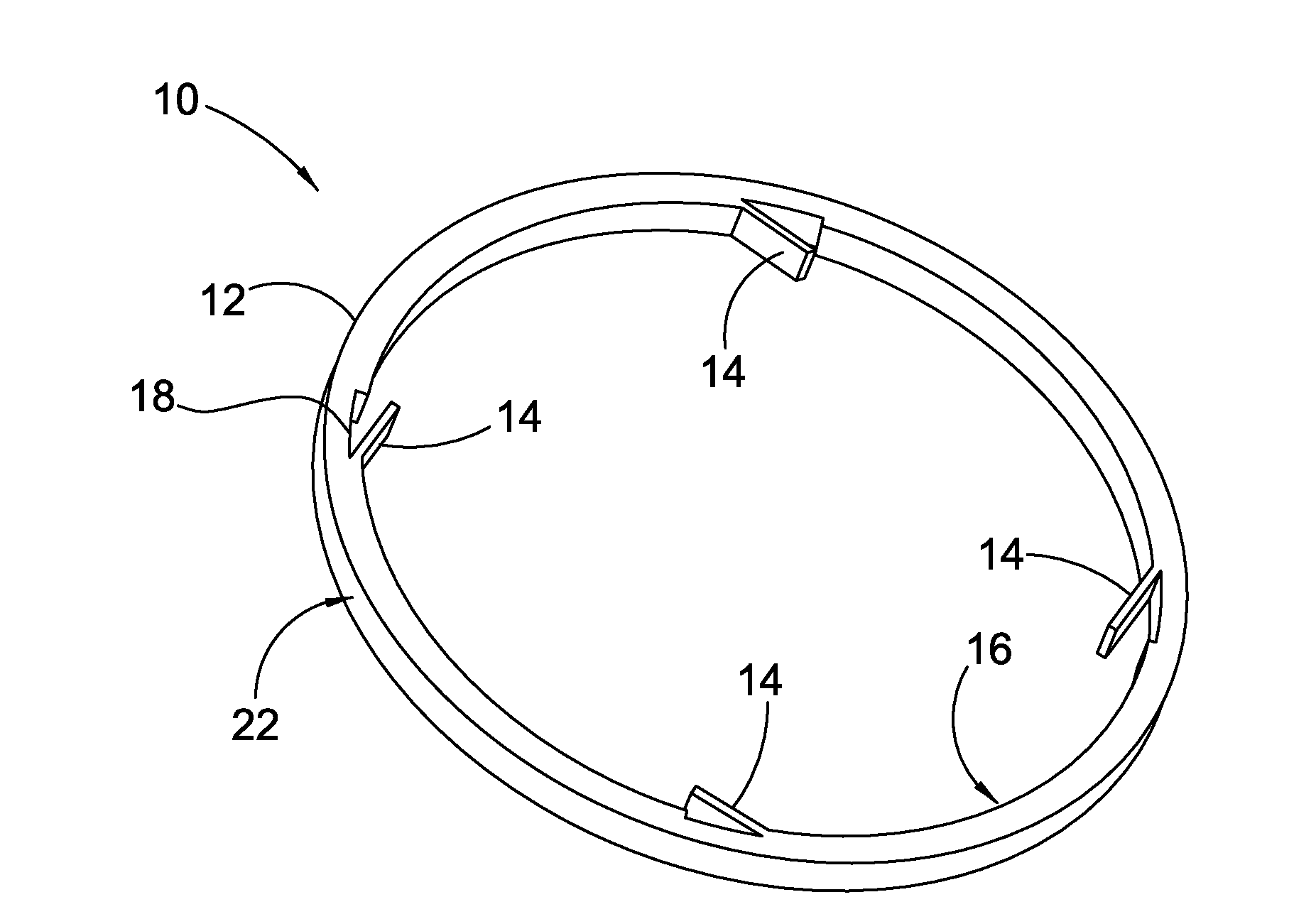
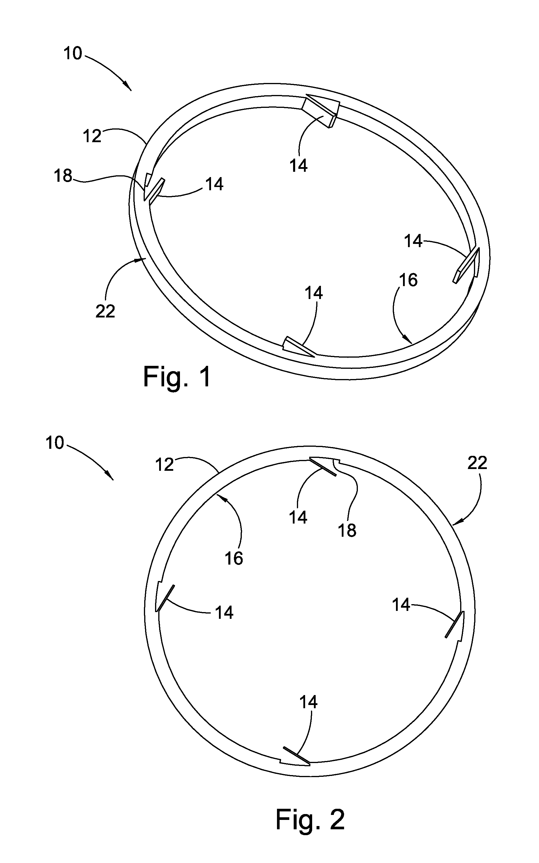
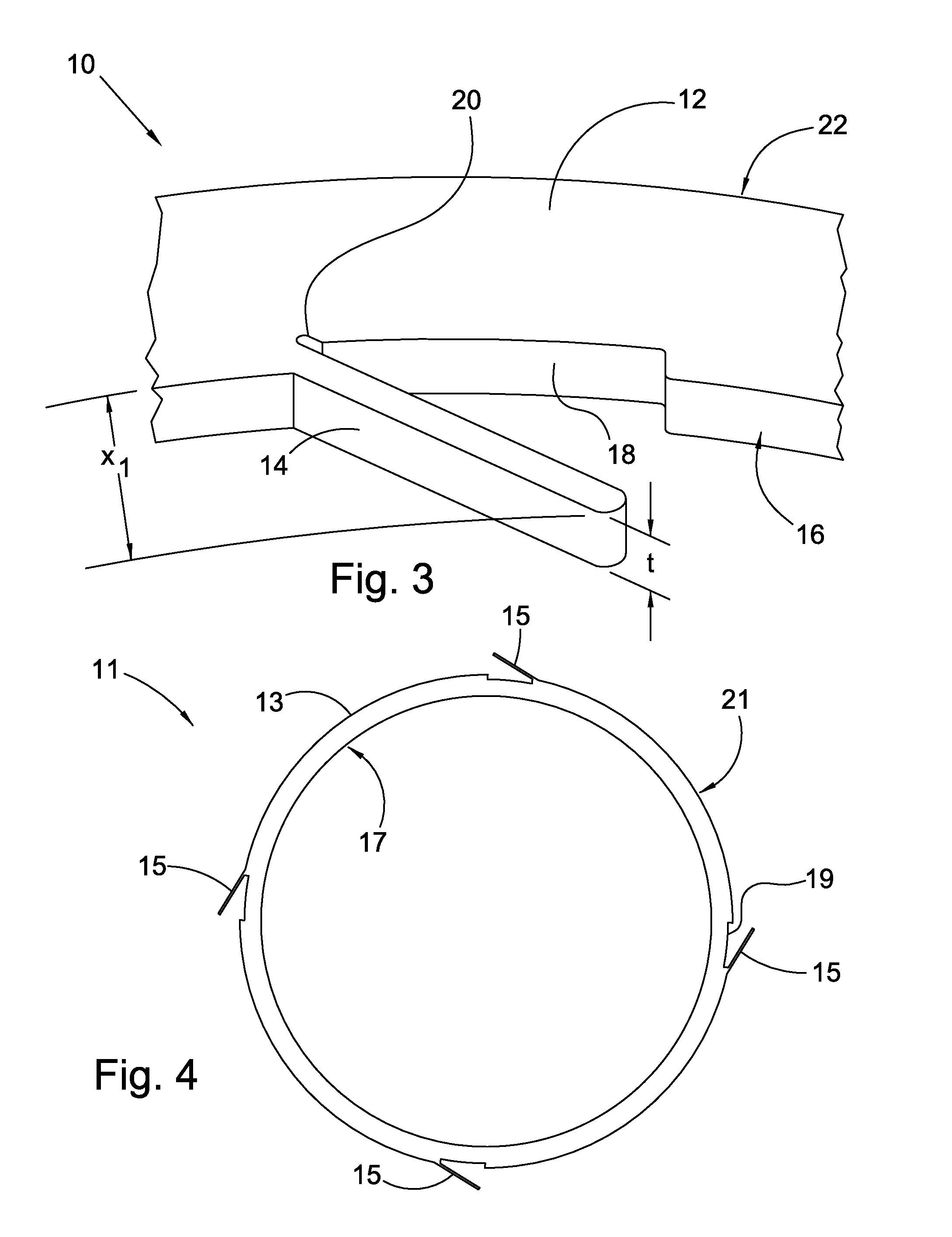
A self-centering floating seal comprising a ring having first and second diameters, wherein the ring is arranged to be installed between first and second gland components, a plurality of tabs protruding from the first diameter, wherein the tabs are operatively arranged to exert a force on the first gland component to create a radial gap between the first diameter and the first gland component, while the second diameter is arranged to engage against the second gland component for forming a sealed interface, a plurality of seats corresponding to the plurality of tabs, wherein each seat forms a recess in the first diameter of the ring for receiving one of the tabs when each tab is flexed toward the ring, and wherein the tabs are substantially equally spaced about the first diameter of the ring, and each of the tabs spans an axial thickness of the ring.

Description

CROSS-REFERENCE TO RELATED APPLICATIONS[0001]This application claims the benefit under 35 U.S.C. §119(e) of U.S. Provisional Application No. 61 / 255,236, filed Oct. 27, 2009.FIELD OF THE INVENTION[0002]The invention broadly relates to sealing mechanisms, more specifically to a centered floating seal, and even more particularly to a centered floating seal for use in an automobile torque converter or power transmission.BACKGROUND OF THE INVENTION[0003]Sealing means are well known in the art. Examples of conventional seals include, for example, floating seals, compression rings, or spring loaded seals. Floating seals do not offer any type of centering during an assembly process. As a result, these seals often fall or sag radially until the inner diameter of the seal contacts the minor diameter of a seal gland, which can result in assembly issues or failure of the seal.[0004]Compression seals do not offer a large degree of radial freedom between adjacent parts, and therefore can not be u...

Claims


Application Information

Patent Timeline
Patent Type & Authority Applications(United States)
IPC IPC(8): F16J15/16
CPCF16J15/441F16H41/24
Inventor ZAUGG, BRIAN
Owner SCHAEFFLER TECH AG & CO KG
Learn More