
Intra-Area Environmental Control System and Intra-Area Environmental Control Method

a control system and environmental control technology, applied in the field of intra-area environmental control system and intra-area environmental control method, can solve the problems of not being able to adapt the method of environmental control devices, the work type of each person is not uniform, and the idea of changing the control method of comfort levels, etc., to achieve the effect of improving the entire comfort in the area

Inactive Publication Date: 2011-04-21
HITACHI LTD
View PDF10 Cites 84 Cited by
  • Summary
  • Abstract
  • Description
  • Claims
  • Application Information

AI Technical Summary

Benefits of technology

[0009](1) The presence / absence and the work status of each person in an intra-area are monitored, and the area is controlled in accordance with the work status of each person, so that comfort can be improved in accordance with the work of each person.
[0013]According to an aspect of the present invention, the work status of each office worker is monitored and environmental control devices are finely controlled in accordance with the work status of each office worker, so that it is possible to improve the entire comfort in the area.

Problems solved by technology

However, there has been no idea of changing a control method of comfort levels in accordance with the situations of behavior in work.
However, the work type of each person is not uniform even in, for example, a space where intellectual work is carried out.
(1) The presence / absence of persons in an area is detected, but the control method of the environmental control devices is not adapted to situations of behavior in work of each person. Thus, the entire comfort of the area is not sufficiently provided.
(2) There is no method or index for recognizing the comfort levels in accordance with behavior in work of each person existing in the area.
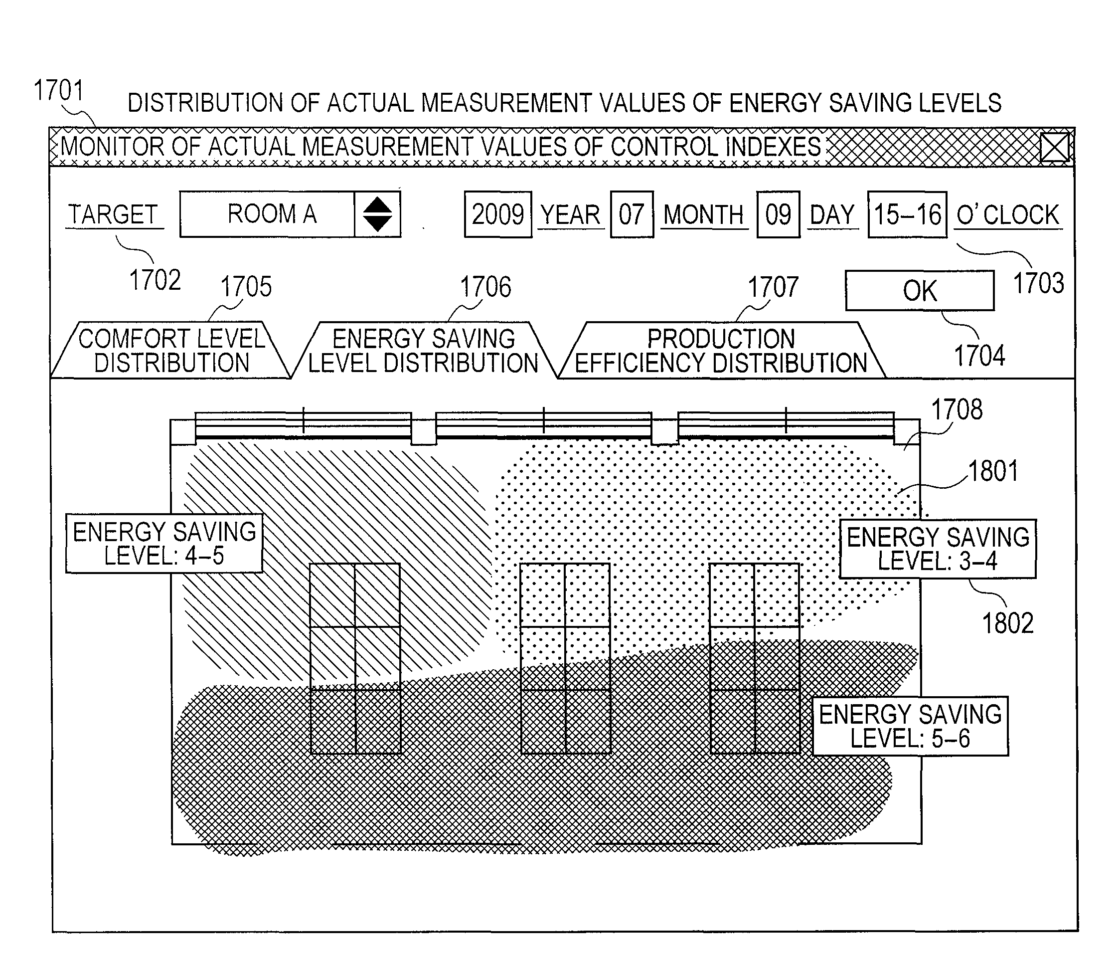
(3) For a manager of environmental control devices, there is no method of easily setting control policies for the environmental control devices on the basis of plural viewpoints including comfort levels and energy saving levels.

Method used


Image

  • Intra-Area Environmental Control System and Intra-Area Environmental Control Method
  • Intra-Area Environmental Control System and Intra-Area Environmental Control Method
  • Intra-Area Environmental Control System and Intra-Area Environmental Control Method

Examples


Embodiment Construction

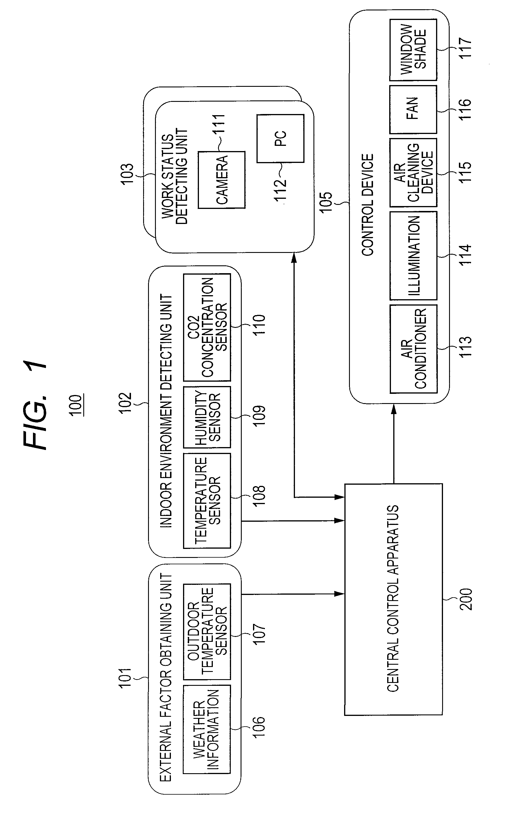
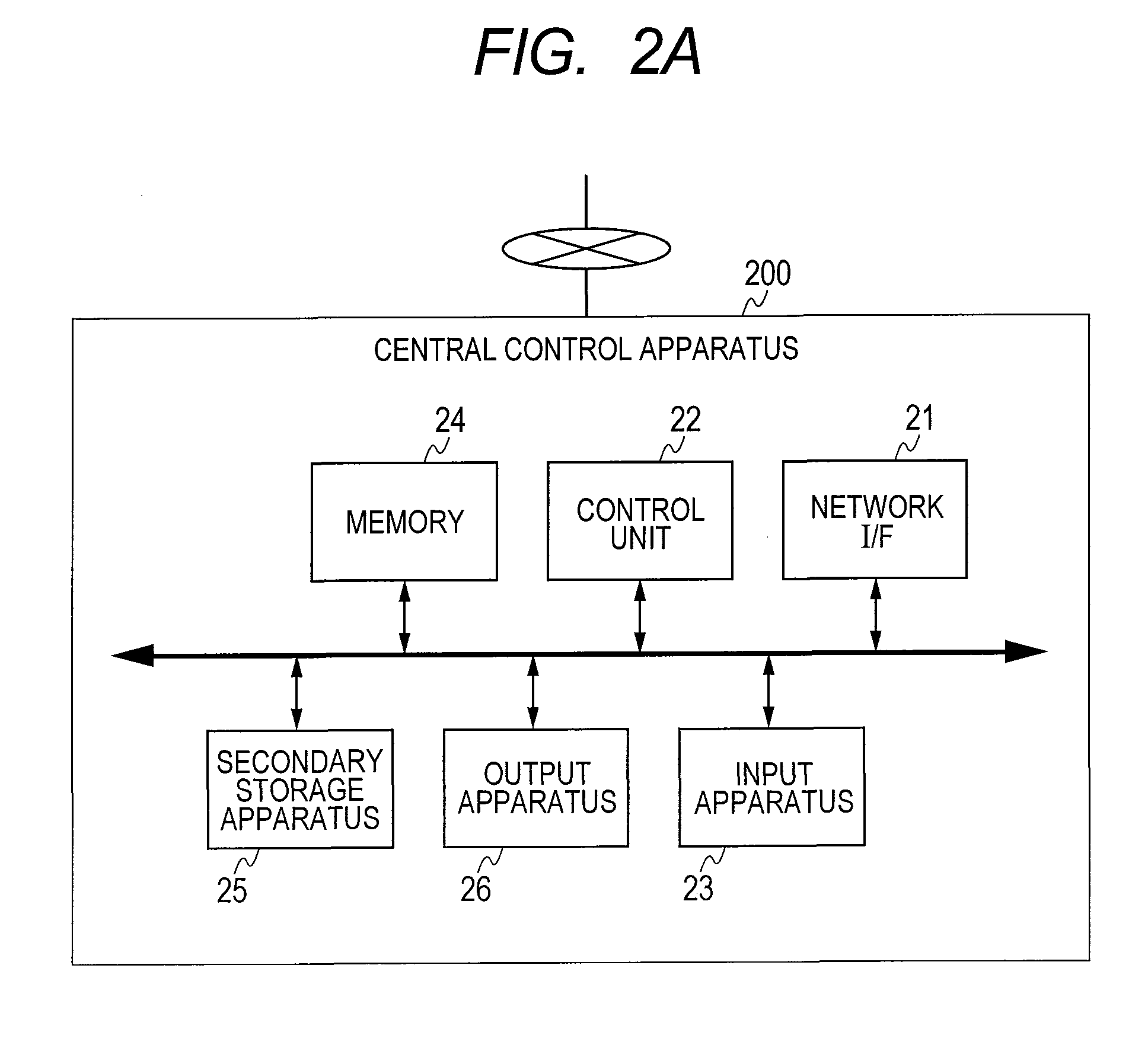
[0035]An environmental control system according to the present invention is a system for controlling environmental devices by which the work status and behavior status of each person in a room of an office building or the like are monitored and the environmental devices are finely controlled in accordance with the statuses to improve comfort. The environmental control system includes a communication unit, a unit for detecting environments, a unit for detecting a work status, a unit for obtaining power consumption, a unit for determining the control of a device, and a unit for transmitting a control signal, whereby enables fine, control in accordance with a work type. In the following description, there will be described an example in which a room of an office building or the like is controlled for each area. Specifically, the environmental control system of the present invention controls environmental devices in which energy saving and comfort are satisfied in an area. The environme...


PUM


Abstract

An environmental control system according to the present invention is a system for controlling environmental devices by which a work status and a behavior status are monitored and the environmental devices are finely controlled in accordance with the statuses to improve comfort. The environmental control system includes a communication unit, a unit for detecting environments, a unit for detecting a work status, a unit for obtaining power consumption, a unit for determining the control of a device, and a unit for transmitting a control signal, and enables fine control in accordance with a work type.

Description

CLAIM OF PRIORITY[0001]The present application claims priority from Japanese Patent Application JP 2009-242473 filed on Oct. 21, 2009, the content of which is hereby incorporated by reference into this application.FIELD OF THE INVENTION[0002]The present invention relates to an intra-area environmental control system and an intra-area environmental control method, and particularly to an environmental control system and an environmental control method in which a relation between work statuses of persons and environmental control devices such as air conditioning devices and illumination devices in an area is comprehensively considered.BACKGROUND OF THE INVENTION[0003]As a conventional and general control method of environmental control devices, an air conditioner is controlled such that the temperature in a room (area) is always kept at a predetermined target temperature. However, there has been also proposed a control method for energy saving such as an intermittent control under whic...

Claims


Application Information

Patent Timeline
IPC IPC(8): G06F1/32G06F1/28
CPCG05B15/02G06Q50/06G06Q10/06G05B2219/2642Y02P80/10Y02P90/82
Inventor TOBA, MINAKOMORI, YASUHIDENAONO, KENEGI, MASASHISAKURAI, TAKAO
Owner HITACHI LTD
Learn More