Leaf chain

Active Publication Date: 2011-04-14
MING CHANG TRAFFIC PARTS MFG
View PDF9 Cites 1 Cited by
  • Summary
  • Abstract
  • Description
  • Claims
  • Application Information

AI Technical Summary

Benefits of technology

[0010]Therefore, the object of the present invention is to provide a leaf chain, which facilitates to prevent the lubricant contained therein from leakage, thereby conducing to a preferable lubricating efficiency and thence extending a serve life of the leaf chain.
[0011]The leaf chain in accordance with the present invention mainly comprises a plurality of links connected together, each of which includes two aligned rollers, at least one first inner plate provided with apertures to pivotally receive the rollers, and two outer plates fixed to the respective rollers and respectively positioned at external sides of the first inner plate. Wherein, two spacers are respectively disposed at both peripheries of the aperture on the first inner plate and annularly disposed on the rollers so as to block a leakage of a lubricant distributed over an interstice formed between each roller and each aperture. Therefore, the inner plates and the rollers preferably avert from abrasion and rustiness, and the using life of the leaf chain could be prolonged.

Problems solved by technology

However, when the leaf chain 1 is applied, components contained therein are subjected to a reciprocal abrasion, thereby resulting in a soaring temperature of the lubricant 2 to decline the adhesion force thereof.
As a result, the lubricating efficiency adapted to the leaf chain 1 is poor, which however influences the integral transmission stability of the leaf chain 1 and increases the abrasion rate between the rollers 12, the first and the second inner plates 13, 14 to accordingly reduce the service life of the same.2. Since the first inner plate 13 would be commonly built to a tolerance to the dimension of the aperture 131 in time of manufacturing, the contacting surface between the first inner plate 13 and the roller 12 would be somewhat uneven that unfavorably incurs a slackened engagement.
Thus, when the leaf chain is operated, such slackened engagement thereof is easily subjected to collision and abrasion.
As a result, an undesirable abrasion would be caused between the roller 12 and the outer plate 15, thence affecting the service life of the same.

Method used


Image

  • Leaf chain
  • Leaf chain
  • Leaf chain

Examples


Embodiment Construction

[0021]Before the present invention is described in greater detail, it should be noted that the like elements are denoted by the similar reference numerals throughout the disclosure.

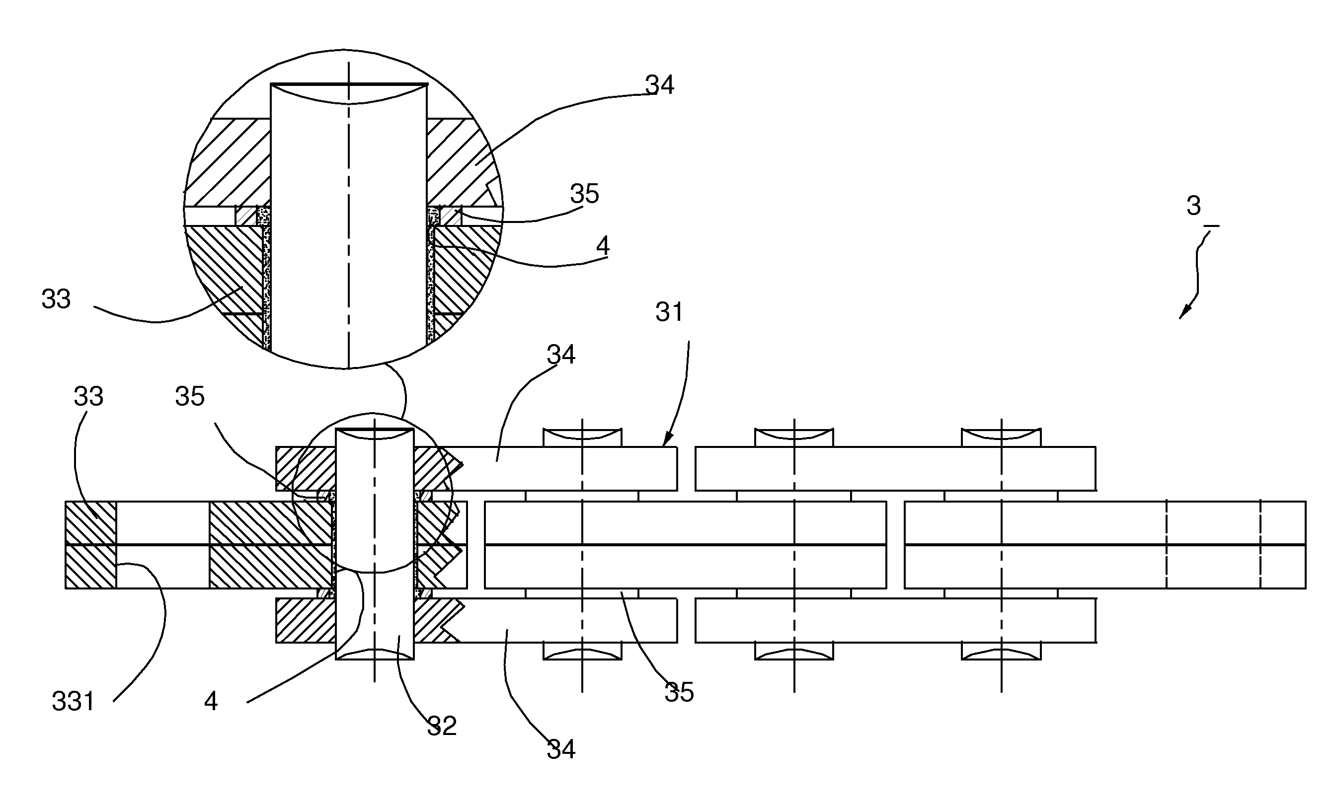
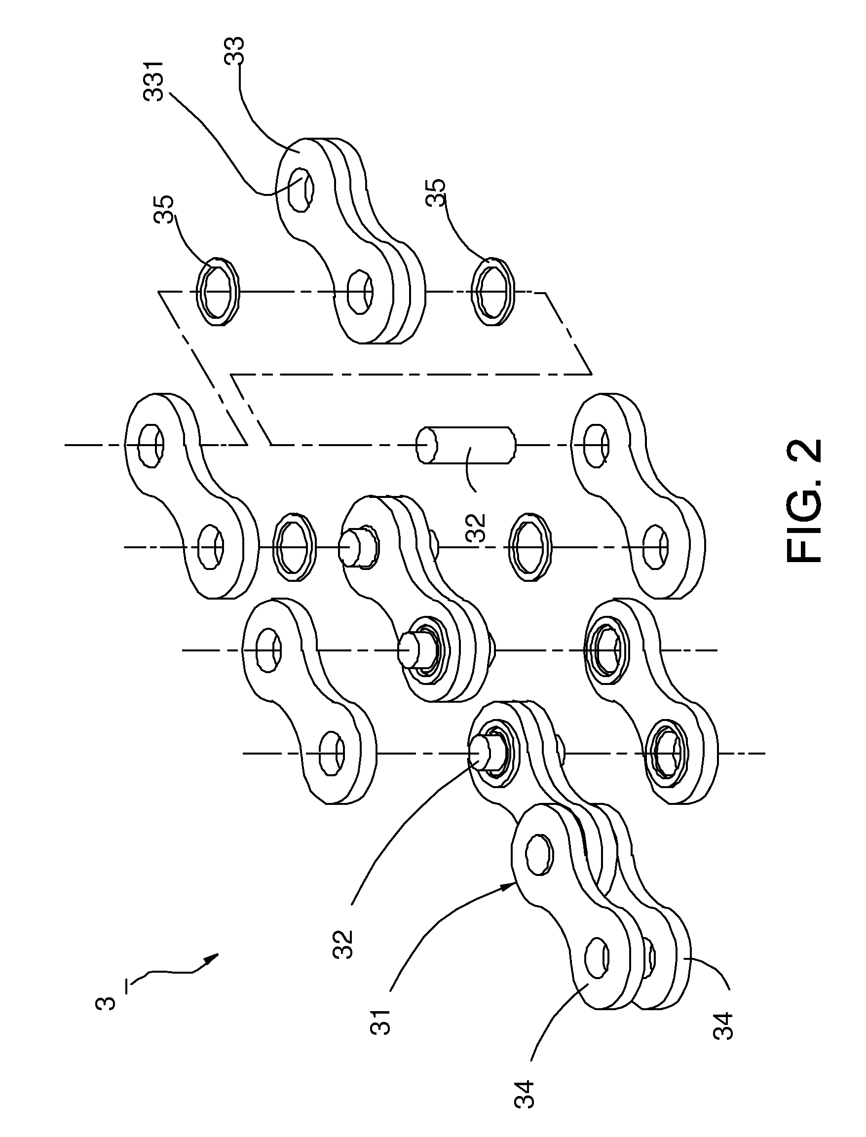
[0022]Referring to FIGS. 2 and 3, a leaf chain 3 of a first preferred embodiment of the present invention comprises a plurality of links 31 connected together, each of which includes two aligned rollers 32, at least one first inner plate 33 pivotally disposed on the rollers 32, and two outer plates 34 fixed to the respective rollers 32 and positioned at the external surfaces of the first inner plate 33. Wherein, a plurality of first apertures 331 defined on the first inner plate 33 that pivotally joints the roller 32 would be penetrated by the rollers 32. Moreover, a lubricant 4 is added within an interstice formed between each roller 32 and each aperture 331.

[0023]Continuing with the aforementioned, a spacer 35 is disposed between the outer plate 34 and the first inner plate 33 as well as annularly dispo...


PUM


Abstract

A leaf chain comprises a plurality of links connected together, each of which includes two aligned rollers, at least one first inner plate provided with apertures to pivotally receive the rollers, and two outer plates fixed to the respective rollers and respectively positioned at external sides of the first inner plate. Wherein, two spacers are respectively disposed at both peripheries of the aperture on the first inner plate and annularly disposed on the rollers so as to block a leakage of a lubricant distributed over an interstice formed between each roller and each aperture.

Description

BACKGROUND OF THE INVENTION[0001]1. Field of the Invention[0002]The present invention relates to a leaf chain, particularly to a leaf chain for machinery with a high loading transmission.[0003]2. Description of the Related Art[0004]Generally, chains are applied to transmit dynamics. With practical applied occasions, various chains with divergent types and structures are designed. For example, the leaf chain is usually applied to the occasion that requires a high driving force, such as the machinery for transmission or for hanging weighty objects.[0005]Referring to FIG. 1, a conventional leaf chain 1 substantially comprises a plurality of links 11 strung together. Each of the links 11 includes two aligned rollers 12, at least one first inner plate 13 pivotally disposed on the rollers 12 (four first inner plates set of lines are adopted in the illustration), a second inner plate 14 provided between any two of the first inner plates 13, and two outer plates 15 respectively fixed to the...

Claims


Application Information

Patent Timeline
IPC IPC(8): F16G13/07F16G13/02
CPCF16G13/08F16G13/02
Inventor HUANG, YI-CHENG
Owner MING CHANG TRAFFIC PARTS MFG
Why Eureka
Try Eureka