Pipe Flange Facing Apparatus and Method

a technology for facing devices and pipes, applied in the direction of turning machine accessories, manufacturing tools, portable lathes, etc., can solve the problems of preventing the use of requiring maintenance of flange interfaces, and large and heavy previous pipe flange facing devices

Active Publication Date: 2011-04-14
ENERPAC TOOL GRP CORP
View PDF29 Cites 29 Cited by
  • Summary
  • Abstract
  • Description
  • Claims
  • Application Information

AI Technical Summary

Problems solved by technology

The flange interfaces require maintenance as they deteriorate over time and can be damaged.
Unfortunately, previous pipe flange facing devices are relatively large and heavy to accommodate the high operating loads provided by the power source.
Such structures prevent the use of previous pipe flange facing devices in “hard to reach” locations or other locations having a limited amount of space.
In addition, some of the power sources, such as air compressors, prevent the use of previous pipe flange facing devices on remote sites without electricity.

Method used


Image

  • Pipe Flange Facing Apparatus and Method
  • Pipe Flange Facing Apparatus and Method
  • Pipe Flange Facing Apparatus and Method

Examples


Embodiment Construction

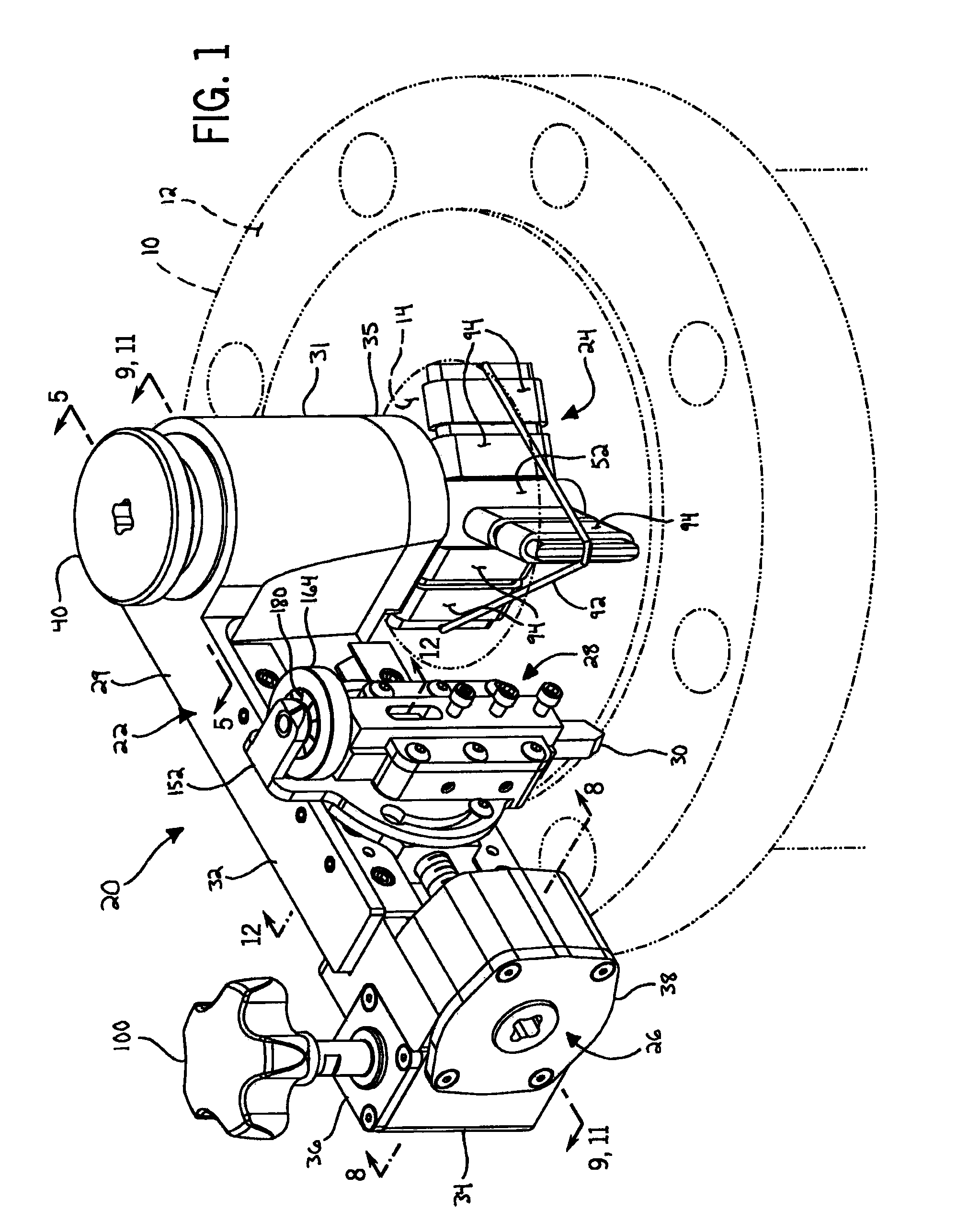
[0026]Referring to now to the drawings and particularly FIGS. 1-4, a pipe flange facing apparatus 20 of the present invention includes a housing 22 that rotatably supports an anchor assembly 24 for securing the apparatus 20 relative to a pipe 10. The pipe flange facing apparatus 20 also includes a feed assembly 26 that drives a tool support assembly 28. The tool support assembly 28 supports a flange facing tool 30 that re-faces (or simply “faces”) a flange 12 of the pipe 10 as the housing 22 rotates about the anchor assembly 24. These components are described in further detail in the following paragraphs, beginning with the housing 22 and proceeding to the tool support assembly 28. A preferred method of using the pipe flange facing apparatus 20 is also described.

[0027]Still referring to FIGS. 1-4, the housing 22 includes an anchor-tool support bracket 29 having an anchor support 31 that defines an internal support shaft passageway 33. The anchor support 31 connects to a housing cap ...


PUM

PropertyMeasurementUnit
sizeaaaaaaaaaa
drive forceaaaaaaaaaa
inner diameteraaaaaaaaaa

Abstract

An apparatus for facing a flange of a pipe comprises a housing and an anchor assembly rotatably supported by the housing. The anchor assembly is configured to engage an inner surface of the pipe. The apparatus further comprises a tool holder translatably supported by the housing. The tool holder is configured to support a facing tool for facing the flange of the pipe. The apparatus further comprises a drive shaft that is rotatable relative to the housing to translate the tool holder relative to the housing. The housing is rotatable relative to the anchor assembly about a first axis in a first direction and the drive shaft is simultaneously rotatable relative to the housing about a second axis in a second direction opposite the first direction to move the tool holder along a spiral path and thereby face the flange of the pipe.

Description

CROSS-REFERENCE TO RELATED APPLICATION[0001]Not applicable.STATEMENT OF FEDERALLY SPONSORED RESEARCH OR DEVELOPMENT[0002]Not applicable.BACKGROUND OF THE INVENTION[0003]This invention relates to a pipe flange facing apparatus, particularly a manual pipe flange facing apparatus.[0004]Many industrial facilities, such as chemical plants, pulp mills, shipyards, oil refineries and the like include pipes that carry various fluids. Pipes in these environments are often constructed in multiple sections. The end of each pipe section includes a flange to connect to that of another pipe section, typically by fasteners or the like. The flange interfaces require maintenance as they deteriorate over time and can be damaged. As such, re-facing operations are typically conducted to repair deteriorated or damaged pipe flanges.[0005]Previous pipe flange facing devices have been designed such that flanges may be repaired on-site (i.e., without having to transport pipes to a repair facility) after simp...

Claims


Application Information

Patent Timeline
Patent Type & Authority Applications(United States)
IPC IPC(8): B23B3/26B23B5/00B23B1/00
CPCB23B3/265B23B5/162Y10T82/22Y10T82/2522Y10T82/10B23C2215/04
Inventor PLACE, BRENT K.ERNEST, PIETER W.
Owner ENERPAC TOOL GRP CORP
Why Eureka
Try Eureka