
Video signal with depth information

Inactive Publication Date: 2011-03-31
KONINKLIJKE PHILIPS ELECTRONICS NV
View PDF7 Cites 13 Cited by
  • Summary
  • Abstract
  • Description
  • Claims
  • Application Information

AI Technical Summary

Benefits of technology

[0011]Since the stripes comprise data elements indicative of the position of the rectangular area of image information within the primary view, it becomes possible to more flexibly accommodate occlusion or side area information into the video signal. Any information about portions of the scene that might be available to the system can be inserted into one or more of such stripes. The video-like characteristics of the signal can be preserved to a large extend, because the stripes comprise familiar data elements indicative of color and depth. Consequently, these data elements may be encoded in a way known in the art of video encoding. This allows addressing backwards compatibility issues. It also allows applying standard video compression methods for information comprised within a stripe.
[0013]Information of rear areas may also be included to further enhance the stereoscopic views. Information of rear areas also improves the possibility to look around objects: the scene may be viewed from very different perspectives, for example to allow a viewer to virtually move through the scene.
[0016]A one-dimensional, line-based representation has the advantage that is enables representation of more erratic shaped objects without unnecessary storage loss. Whereas a two-dimensional, i.e. multi-line based representation has the advantage that it enables improved compression of stripe data as spatial redundancy within a stripe can be exploited using e.g. block based compression schemes.
[0020]For example, tuple (1) above includes two p-values, one for the color data-element and one for the depth data-element. Tuple (2) in turn represents a situation where the color data-elements are spread over two lines, and wherein the color sample points 1 and 2 are on the top line, and sample points 3 and 4 are located directly below on the bottom line. As the points 1 and 3 have the same offset within their respective line, a single p-value here suffices. The tuples (3) and (4) in turn do not comprise a separate p-value for the depth data-element. In the tuples (3) and (4) the p-value for the depth data-element is derivable from the p-values of the color data-elements. Finally tuple (5) allows full control of the position of sampling points within the rectangular area of image information within the primary view.

Problems solved by technology

The above method however is somewhat limited with respect to the information provided and may not provide sufficient information for accurate rendering.

Method used


Image

  • Video signal with depth information
  • Video signal with depth information
  • Video signal with depth information

Examples


Embodiment Construction

[0044]In recent years, much effort has been put in the development of 3D displays and data representations suitable to drive such displays. Auto-stereoscopic 3D displays do not require the viewer to wear special eyewear (such as the red / green glasses), but usually rely on displaying more than two views which allow users to freely look around the scene which is displayed and perceive depth because their left and right eyes “see” two of these different views. Since displays can vary in the number of views displayed, and also in other attributes, such as the depth range they can portray, a data format which is independent of such differences is needed. The image-and-depth format has been adopted in MPEG-C part 3.

[0045]While the image-and-depth format is suitable for the first generation 3D displays, which have moderate depth range capabilities, it needs to be extended in order to allow for more look-around and less so-called occlusion artifacts. However, occlusion artifacts may also oc...


PUM


Abstract

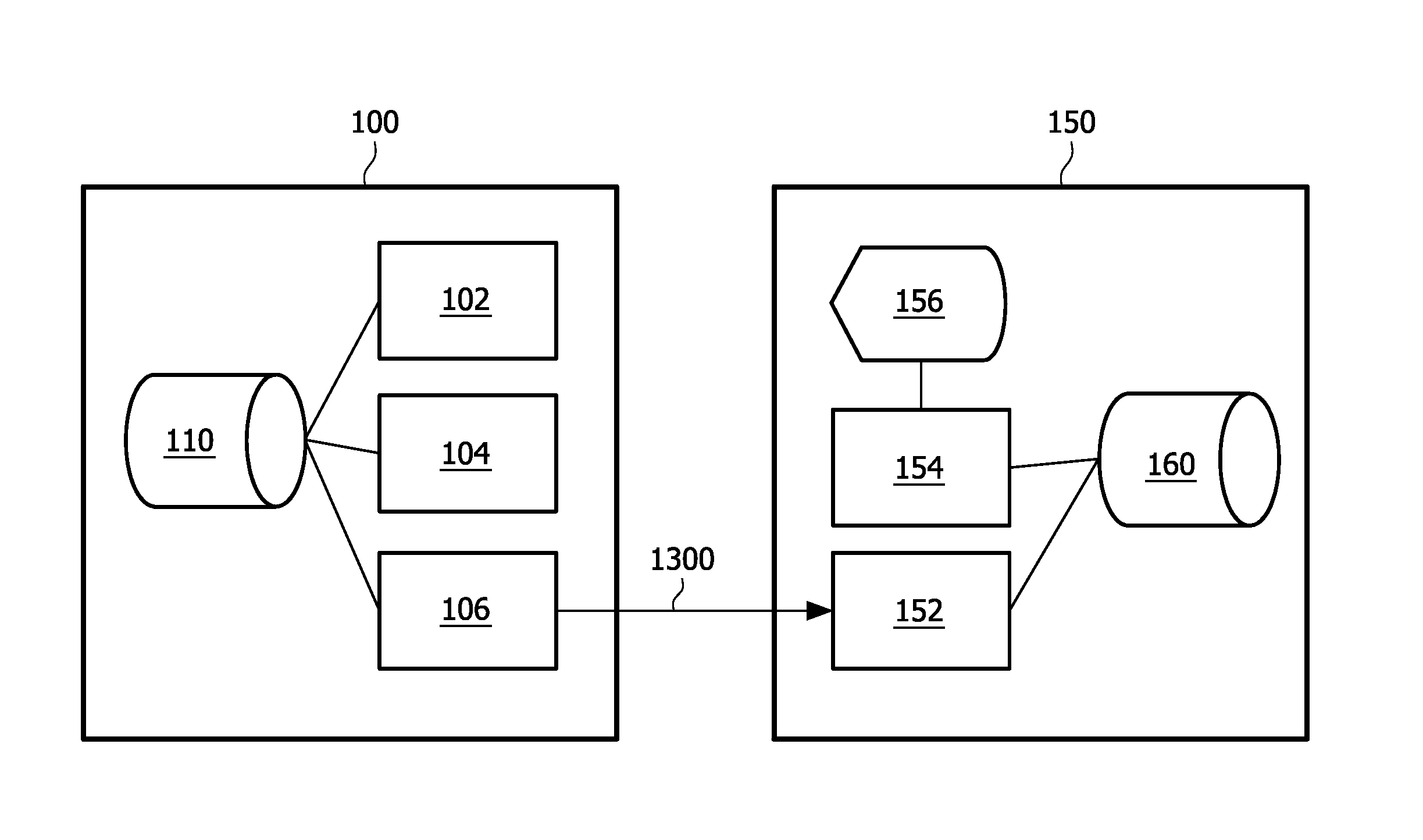
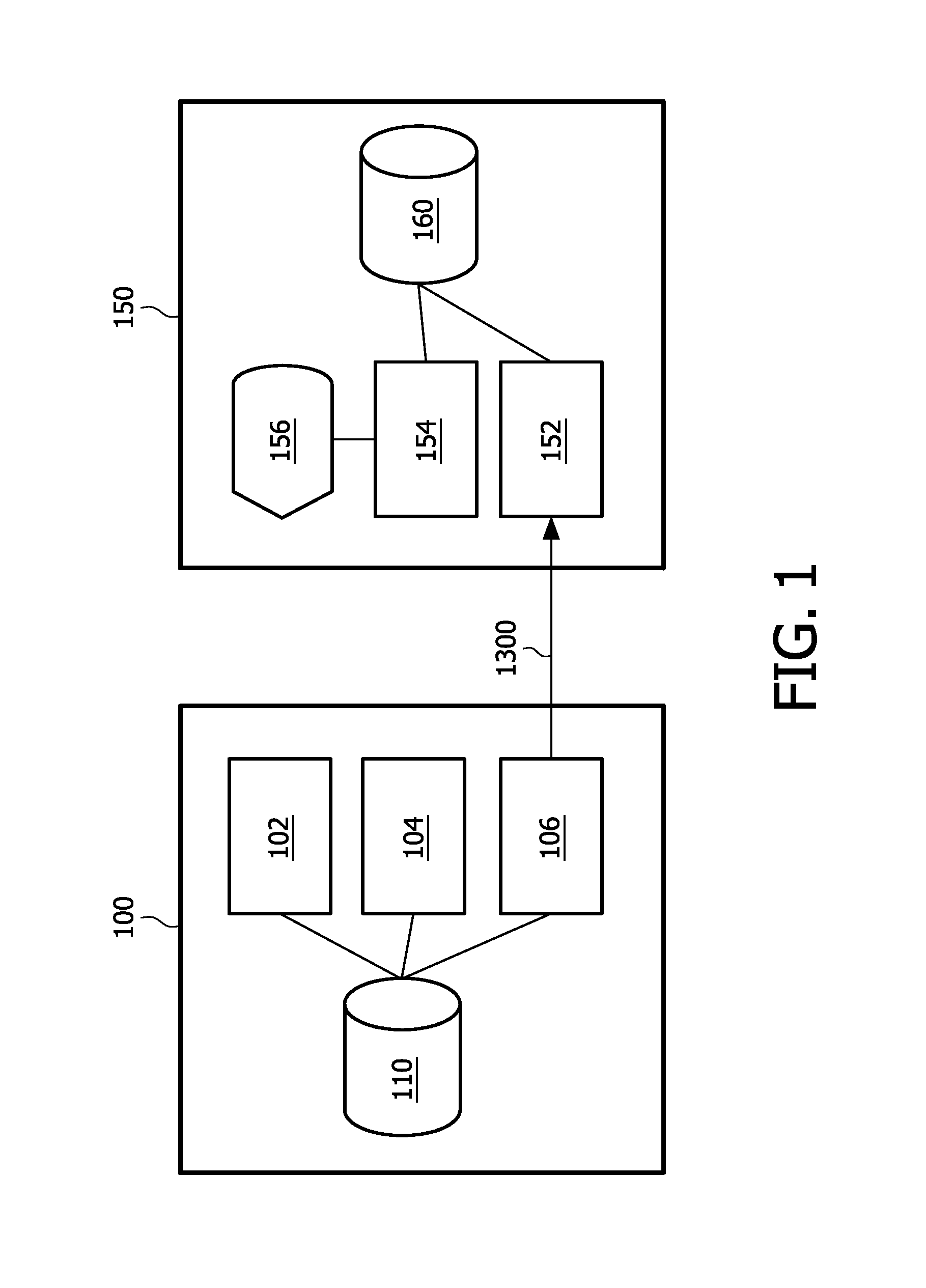
A system (100) for generating a signal (1300) representing a three dimensional scene from a primary view, comprising a sequence generator (104) for generating a sequence of stripes defining at least part of the representation of the three dimensional scene from the primary view and a signal generator (106) for generating a video signal comprising the sequence of stripes. Each stripe in turn represents a rectangular area of image information comprising data elements defining a color, a depth and a position of the rectangular area of image information, wherein the color and depth data elements for each stripe are derived from surface contour information of at least one object in the scene and the position data element is derived from the position of the surface contour information of the at least one object within the primary view. In this signal at least one stripe of the sequence of stripes represents surface contour information of the at least one object selected from an occluded area or a side area of the at least one object in the scene.

Description

FIELD OF THE INVENTION[0001]The invention relates to a video signal with depth information. The invention also relates to methods and systems for generating a video signal with depth information and rendering a video signal with depth information.BACKGROUND OF THE INVENTION[0002]Since the introduction of display devices, a realistic 3-D display device has been a dream for many. Many principles that should lead to such a display device have been investigated. One such principle is a 3-D display device based on binocular disparity only. In these systems the left and right eye of the viewer perceives another perspective and consequently, the viewer perceives a 3-D image. An overview of these concepts can be found in the book “Stereo Computer Graphics and Other True 3-D Technologies”, by D. F. McAllister (Ed.), Princeton University Press, 1993. For example, shutter glasses may be used in combination with for instance a CRT. If the odd frame is displayed, light is blocked for the left ey...

Claims


Application Information

Patent Timeline
IPC IPC(8): H04N13/00
CPCH04N13/0029G06T7/0075H04N13/0275G06T7/593H04N13/275H04N13/139
Inventor BARENBRUG, BART GERARD BERNARDROELEN, WALTHERUS ANTONIUS HENDRIKUS
Owner KONINKLIJKE PHILIPS ELECTRONICS NV
Learn More