
Display device and television receiver

Inactive Publication Date: 2011-03-10
SHARP KK
View PDF5 Cites 6 Cited by
  • Summary
  • Abstract
  • Description
  • Claims
  • Application Information

AI Technical Summary

Benefits of technology

[0037]According to the display device of the present invention, high display quality can be achieved because display uneveness is less likely to occur even when driving the display device by periodically inverting the voltage polarity of driving signals. Furthermore, the television receiver of the present invention includes the display device in which the display uneveness is less likely to occur and thus high display quality without uneveness in television images can be achieved.

Problems solved by technology

The pixel electrodes between which the parasitic capacitance exists may electrically influence each other and unwanted voltage variations may occur.
Such a voltage variation affects the brightness of the display images and thus display uneveness may occur.

Method used


Image

  • Display device and television receiver
  • Display device and television receiver
  • Display device and television receiver

Examples


first embodiment

[0082]The first embodiment of the present invention will be explained with reference to FIGS. 1 to 9. In this embodiment, a television receiver TV including a liquid crystal display device 10 will be used as an example.

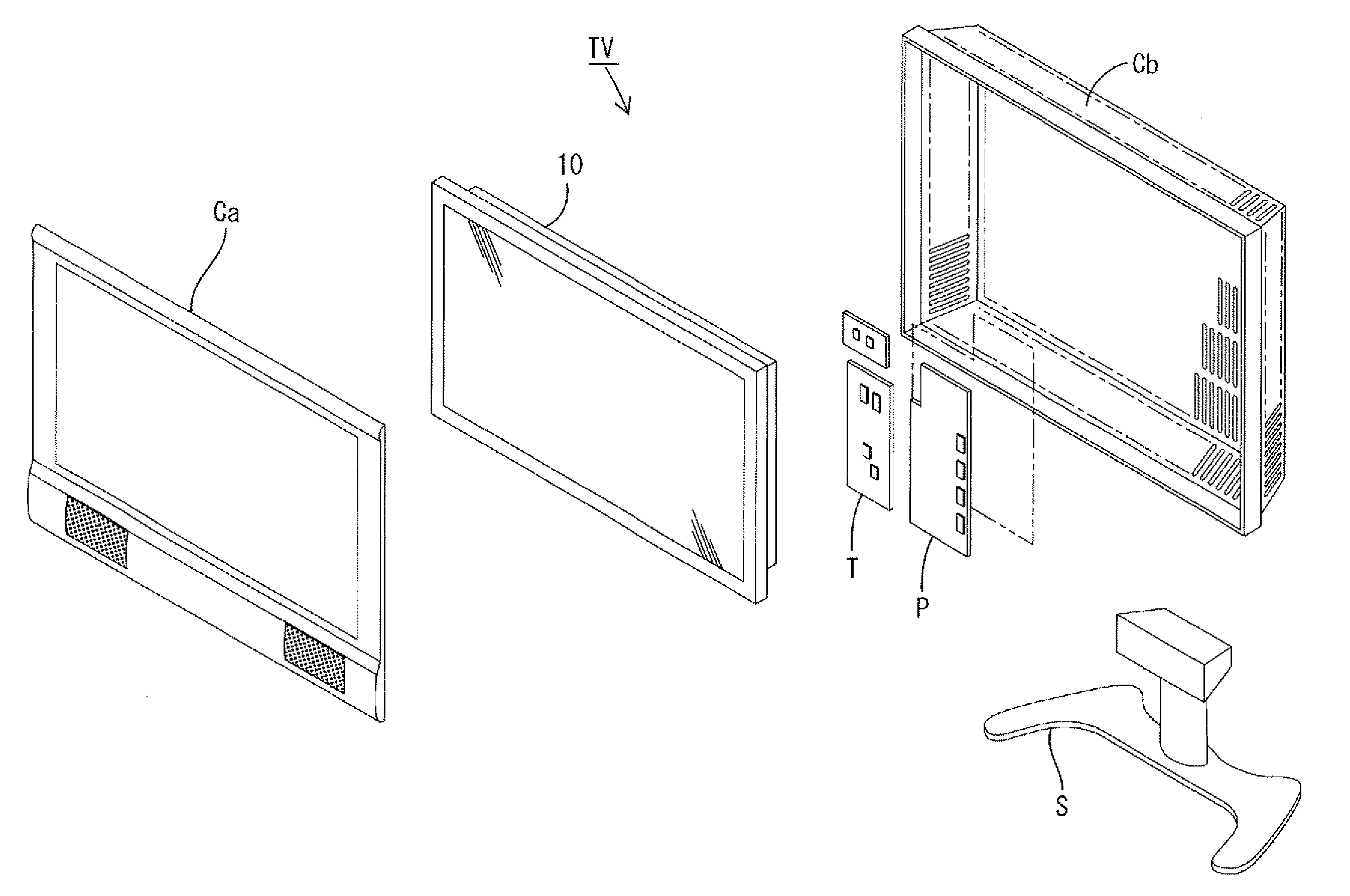
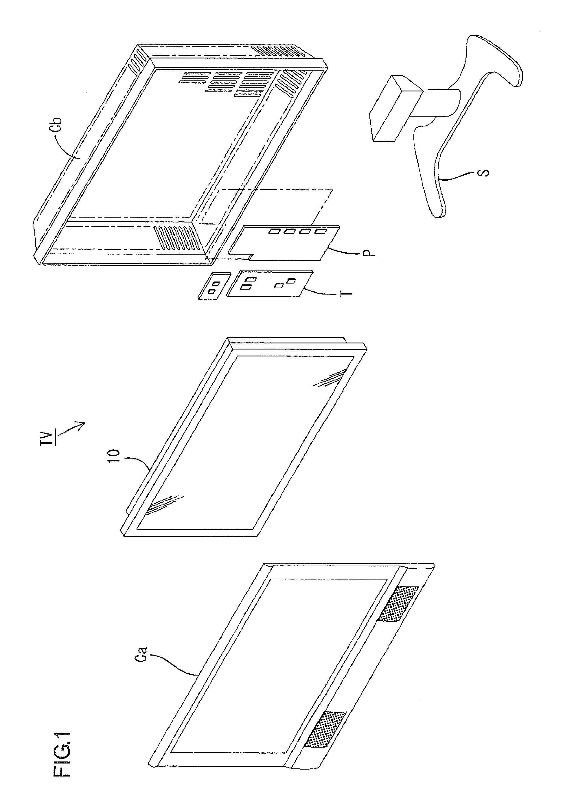
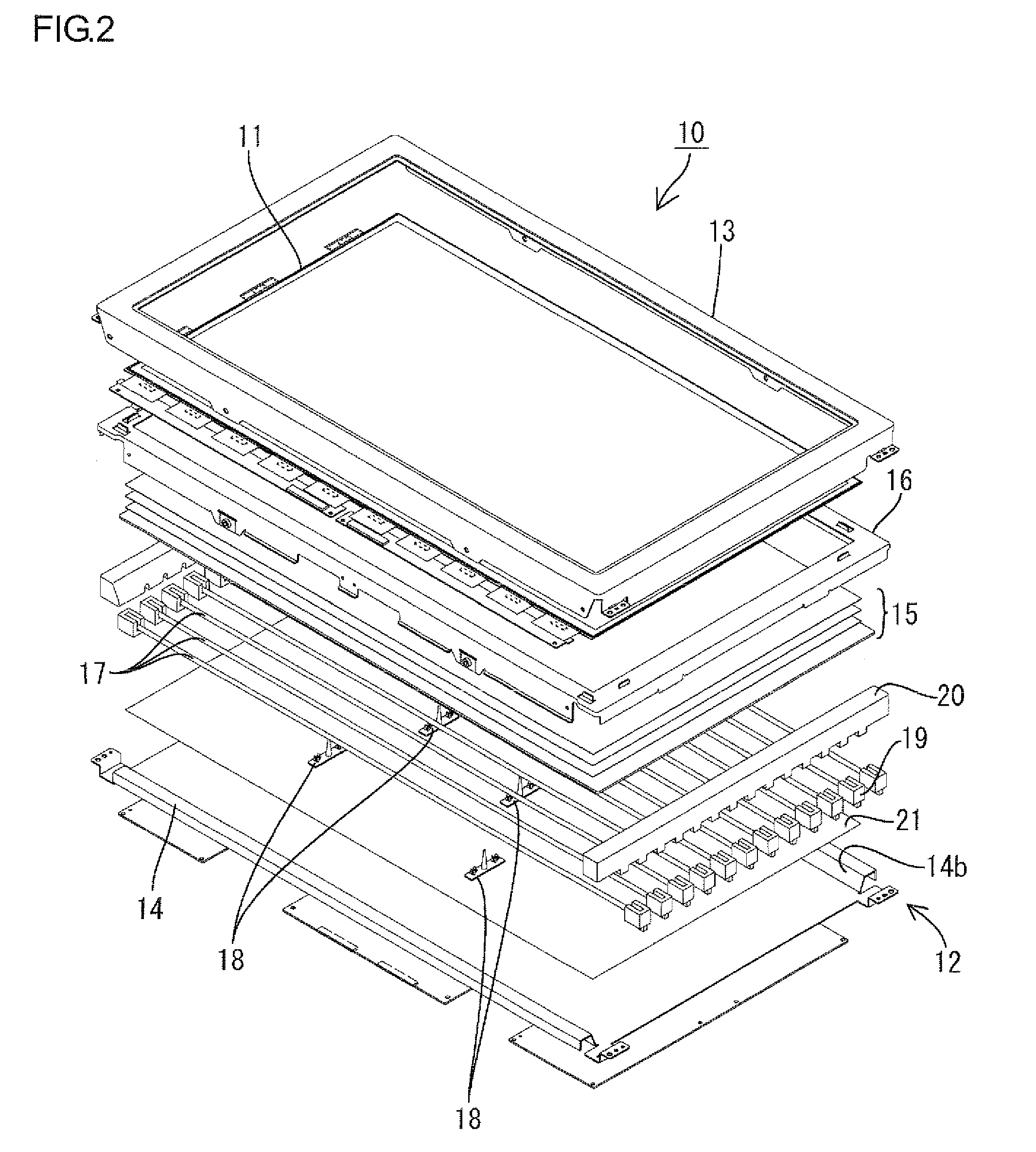
[0083]FIG. 1 is an exploded perspective view illustrating a general construction of the television receiver of this embodiment. FIG. 2 is an exploded perspective view illustrating a general construction of the liquid crystal display device. FIG. 3 is a cross-sectional view of the liquid crystal display device in FIG. 2 along the long-side direction thereof.

[0084]As illustrated in FIG. 1, the television receiver TV of this embodiment includes a liquid crystal display device 10, front and rear cabinets Ca, Cb that house the liquid crystal display device 10 therebetween, a power source P, a tuner T for receiving TV broadcasting and a stand S. The liquid crystal display device (display device) 10 has a landscape rectangular overall shape and housed in a vertical position....

second embodiment

[0150]The second embodiment of the present invention will be explained with reference to FIGS. 14 to 17. The difference between the first embodiment and this embodiment is that the shield electrodes are disposed on the gate signal lines but other configurations are the same. The same parts as the first embodiment will be indicated by the same symbols and will not be explained.

[0151]FIG. 14 is a plan view schematically illustrating wiring patterns on an array board included in the liquid crystal display device according to is embodiment. FIG. 15 is a magnified plan view of relative part of the array board in FIG. 14.

[0152]As illustrated in FIGS. 14 and 15, an array board 60 includes signal lines arranged in a grid and rectangular pixel electrodes 61 arranged in a matrix such that each pixel electrode 61 is surrounded by the signal lines. The signal lines include the data signal lines 43 that extend in the column direction (the vertical direction in FIGS. 14 and 15) on the array board...

third embodiment

[0184]The third embodiment of this invention will be explained with reference to FIGS. 23 to 26. The difference between this embodiment and the first and the second embodiments is that the shield electrodes are electrically connected to the common electrode. Other configurations are the same as the above embodiments. The same parts as the above embodiments will be indicated by the same symbols and will not be explained.

[0185]FIG. 23 is a plan view schematically illustrating wiring patterns on an array board included in the liquid crystal display device according to this embodiment. FIG. 24 is a magnified cross-sectional view illustrating a central part of screen of the liquid crystal panel. FIG. 25 is a magnified cross-sectional view illustrating an end part of screen of the liquid crystal panel.

[0186]As illustrated in FIG. 23, an array board 70 includes rectangular pixel electrodes 41 arranged in a matrix and signal lines arranged in a grid such that each signal line is located bet...


PUM


Abstract

A display device 10 of the present invention includes a plurality of gate signal lines 45, a plurality of data signal lines 43, pixel electrodes 41, hold capacitor lines 46 and a common electrode 36. The data signal lines 43 extend in a direction that crosses the gate signal lines 45. Each pixel electrode 41 is surrounded by the gate signal lines 45 and the gate signal lines 43. The hold capacitor lines 46 are configured such that hold capacitances appear between the pixel electrodes 41 and the hold capacitor lines 46. The common electrode 36 is arranged so as to face the pixel electrodes 41. Conductive parts 48 are provided on the gate signal lines 45 or the hold capacitor lines 46 between the adjacent pixel electrodes 41, 41. The conductive parts 48 are electrically isolated from the pixel electrodes 41 and electrically connected to at least one of the gate lines 45, the hold capacitor lines 46 and the common electrode 36.

Description

TECHNICAL FIELD[0001]The present invention relates to a display device and a television receiver.BACKGROUND ART[0002]A liquid crystal display device including a plurality of gate signal lines and a plurality of data signal lines arranged in a grid, and pixel electrodes arranged such that each of them is surrounded by those signal lines is known as an active-matrix liquid crystal display device. Data signals are fed to the pixel electrodes via switching components. In such a liquid crystal display device, liquid crystal components are deteriorated due to electrochemical reaction that occurs when a DC voltage is applied. AC drive (hereinafter also referred to as inversion drive) that periodically inverts a voltage polarity of application voltage of the data signal is preferable to drive the liquid crystal display device over a long period of time.[0003]If the voltage polarity is inverted for every frame in the active-matrix liquid crystal display device, potentials at pixels vary due ...

Claims


Application Information

Patent Timeline
IPC IPC(8): H04N3/14
CPCG02F1/136286G02F1/136213
Inventor YAMADA, NAOSHITSUBATA, TOSHIHIDE
Owner SHARP KK
Learn More