
Compact optical fiber splice holder device

Active Publication Date: 2011-03-03
CORNING RES & DEV CORP
View PDF25 Cites 44 Cited by
  • Summary
  • Abstract
  • Description
  • Claims
  • Application Information

AI Technical Summary

Benefits of technology

[0009]The above summary of the present invention is not intended to describe each illustrated embodiment or every implementatio

Problems solved by technology

However, as fiber optics are being deployed deeper into the metro and access areas of the network, splicing in these areas of the network are often performed in the air, in cramped closets, and in difficult-to-maneuver locations.
Fusion splicing in these types of locations is difficult, and often there is no power available for fusion splicing machine, thus requiring battery power.
Also, if many locations are scheduled in a given day, many different installation crews will require fusion splicing machines, resulting in a capital investment for the installation company.

Method used


Image

  • Compact optical fiber splice holder device
  • Compact optical fiber splice holder device
  • Compact optical fiber splice holder device

Examples


Embodiment Construction

[0023]In the following Detailed Description, reference is made to the accompanying drawings, which form a part hereof, and in which is shown by way of illustration specific embodiments in which the invention may be practiced. In this regard, directional terminology, such as “top,”“bottom,”“front,”“back,”“leading,”“forward,”“trailing,” etc., is used with reference to the orientation of the Figure(s) being described. Because components of embodiments of the present invention can be positioned in a number of different orientations, the directional terminology is used for purposes of illustration and is in no way limiting. It is to be understood that other embodiments may be utilized and structural or logical changes may be made without departing from the scope of the present invention.

[0024]The present invention is directed to an optical fiber splice holder device. In particular, the optical fiber splice holder device of the exemplary embodiments is of rugged construction, compact leng...


PUM


Abstract

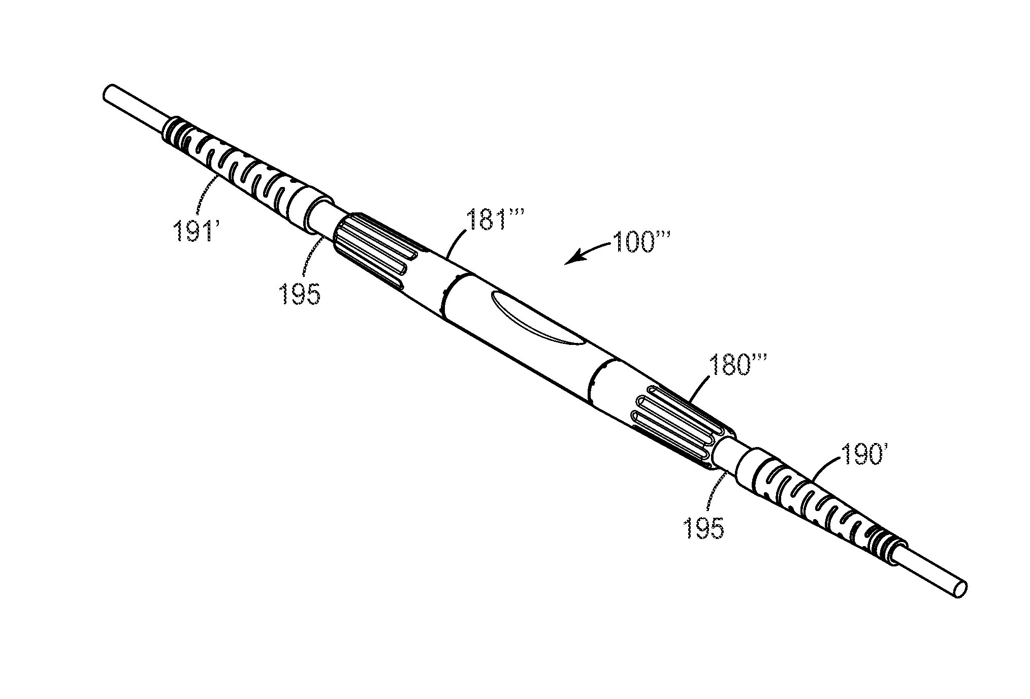
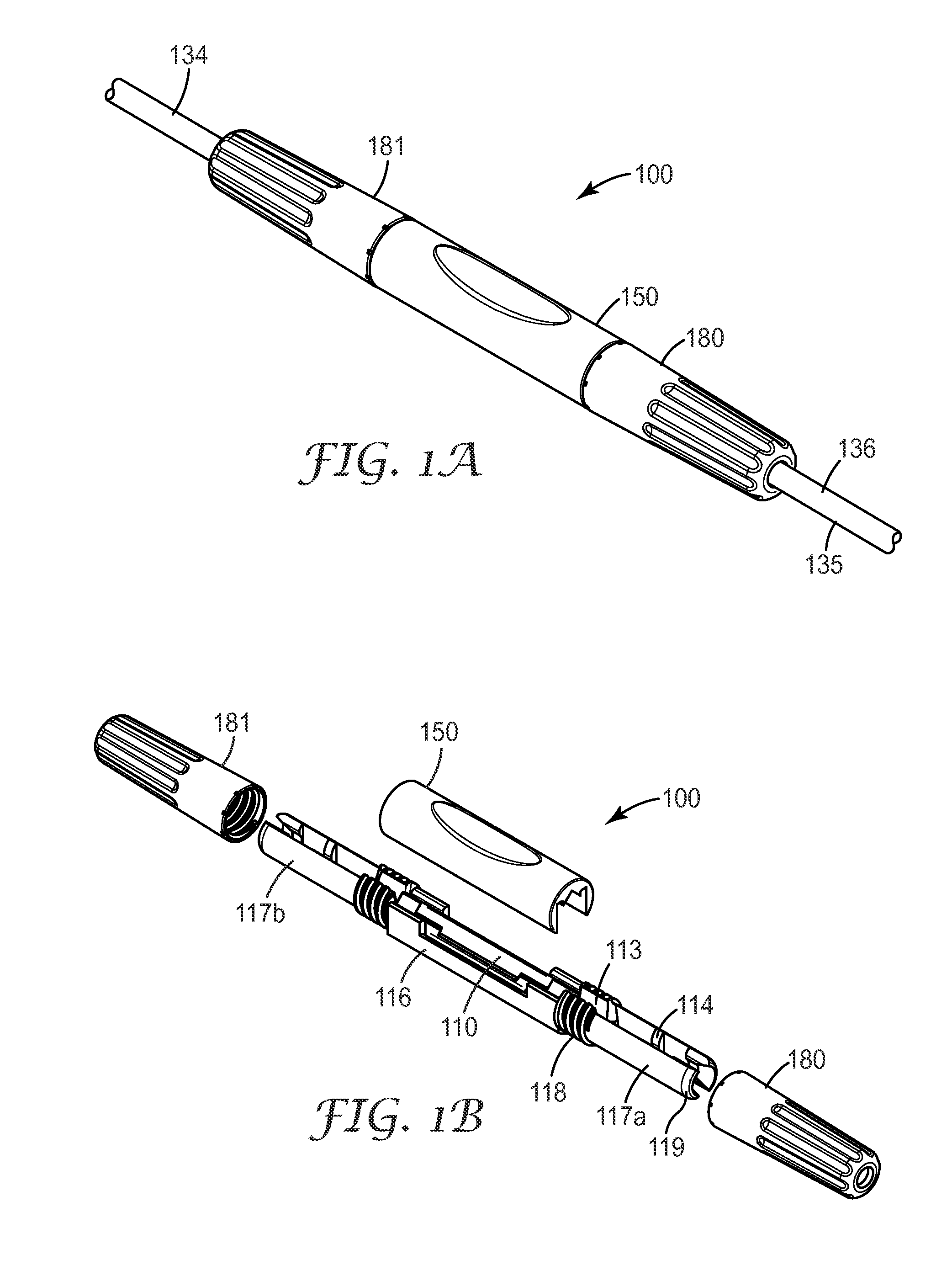
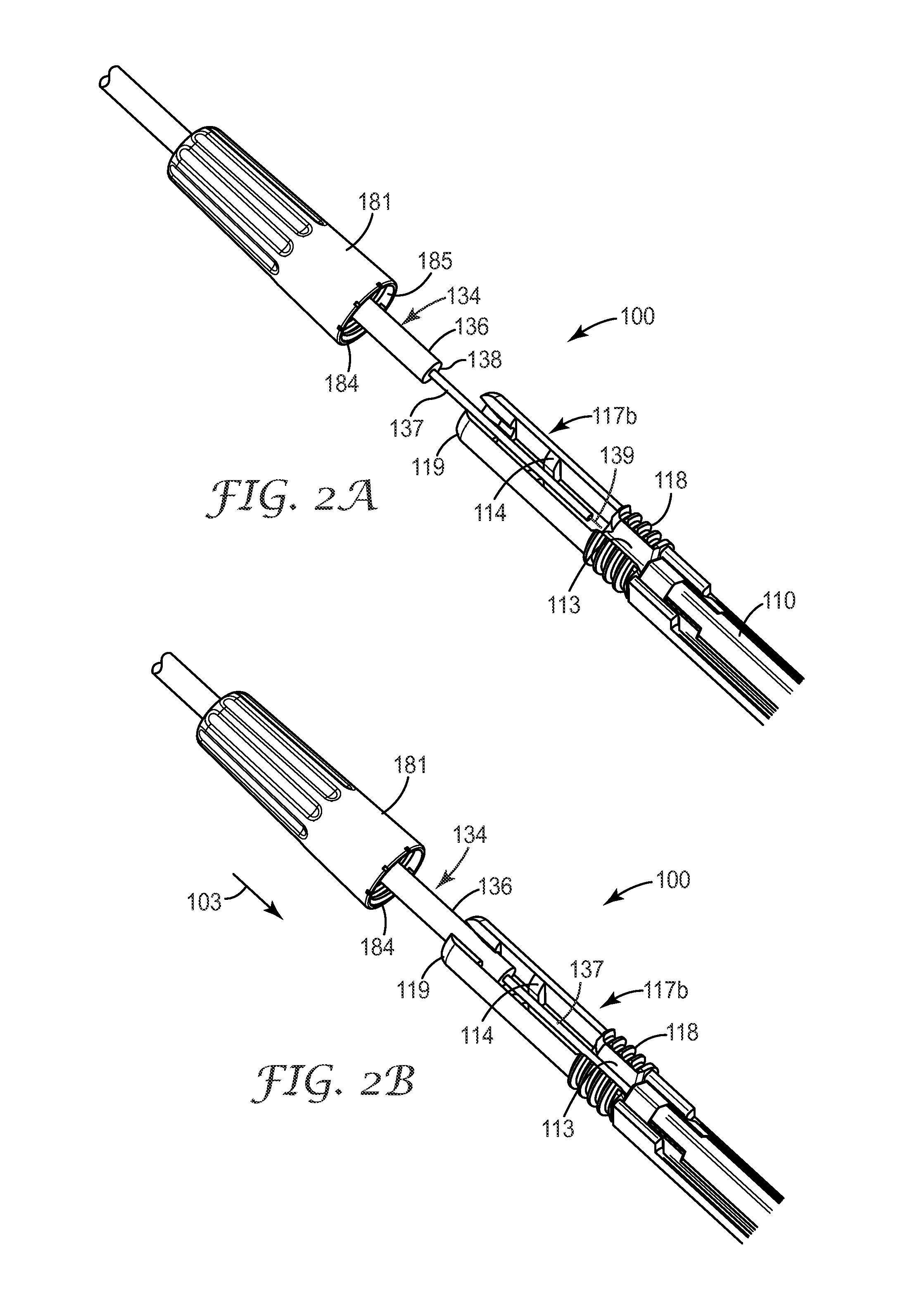
An optical fiber splice holder device for connecting jacketed optical fiber cables includes a cover and a main body that houses a splice device therein. The splice device is configured to splice a first fiber end to a second fiber end. The main body also includes first and second fiber jacket clamping portions disposed at first and second ends of the main body to clamp a respective fiber's jacket portion that surrounds a portion of the respective fiber upon actuation. The optical fiber splice device also includes first and second fiber jacket boots that are attachable to the main body at the first and second ends of the main body. The boots each actuate the respective fiber jacket clamping regions of the optical fiber cables upon attachment to the main body.

Description

BACKGROUND[0001]1. Field of the Invention[0002]The present invention is directed to a compact optical fiber splice holder device.[0003]2. Related Art[0004]Mechanical devices for connecting and / or splicing optical fibers for the telecommunications industry are known. These devices can be part of an optical fiber network such as a FTTH (Fiber to the Home) network. For example, conventional devices are described in U.S. Pat. Nos. 4,824,197; 5,102,212; 5,138,681; 5,159,653; 5,337,390; and 5,155,787.[0005]Another preferred conventional splicing method is fusion splicing. In large deployments, many splices are required to be made in many different areas of the city at the same time. However, as fiber optics are being deployed deeper into the metro and access areas of the network, splicing in these areas of the network are often performed in the air, in cramped closets, and in difficult-to-maneuver locations. Fusion splicing in these types of locations is difficult, and often there is no p...

Claims


Application Information

Patent Timeline
IPC IPC(8): G02B6/00
CPCG02B6/3838G02B6/3887G02B6/3858G02B6/3636G02B6/3806G02B6/3888G02B6/38875
Inventor PARK, CHANSOOLLARSON, DONALD K.
Owner CORNING RES & DEV CORP
Learn More