
Ceiling mount LED lamp

a led lamp and ceiling mount technology, applied in the field of lamps, can solve the problems of not meeting the demand of environmental protection, wasting energy on foregoing luminaires, and crowding and discordant spaces, and achieve the effects of convenient assembly and disassembly, convenient mass production, and simple structur

Inactive Publication Date: 2011-03-03
MAXRAY OPTICAL TECH +1
View PDF8 Cites 31 Cited by
  • Summary
  • Abstract
  • Description
  • Claims
  • Application Information

AI Technical Summary

Benefits of technology

[0013]In accordance with the foregoing embodiment, the present invention provides a ceiling mount LED lamp. The ceiling mount LED lamp has a simple structure and can be conveniently assembled and disassembled. Further, it is cheap and suitable for mass production. Furthermore, the present invention advantageously applies LED units in ceiling mount lamps to achieve a higher brightness and better energy efficiency. Comparing with the conventional light sources, the ceiling mount LED lamp of the present invention saves about 60% of power, and further has the advantages of no UV and IR radiation, no flickering, no stroboflash, and quick start.

Problems solved by technology

When such a chandelier is provided in a home with a 2.7 m floor height, the space may be looked crowd and discordant.
Both of the foregoing luminaries disadvantageously consume much energy, and do not satisfy the demand of environmental protection.
However, LED lamps are not yet applied in the field of ceiling mount lamps.

Method used


Image

  • Ceiling mount LED lamp
  • Ceiling mount LED lamp
  • Ceiling mount LED lamp

Examples


Embodiment Construction

[0018]The accompanying drawings are included to provide a further understanding of the invention, and are incorporated in and constitute a part of this specification. The drawing illustrates embodiments of the invention and, together with the description, serves to explain the principles of the invention.

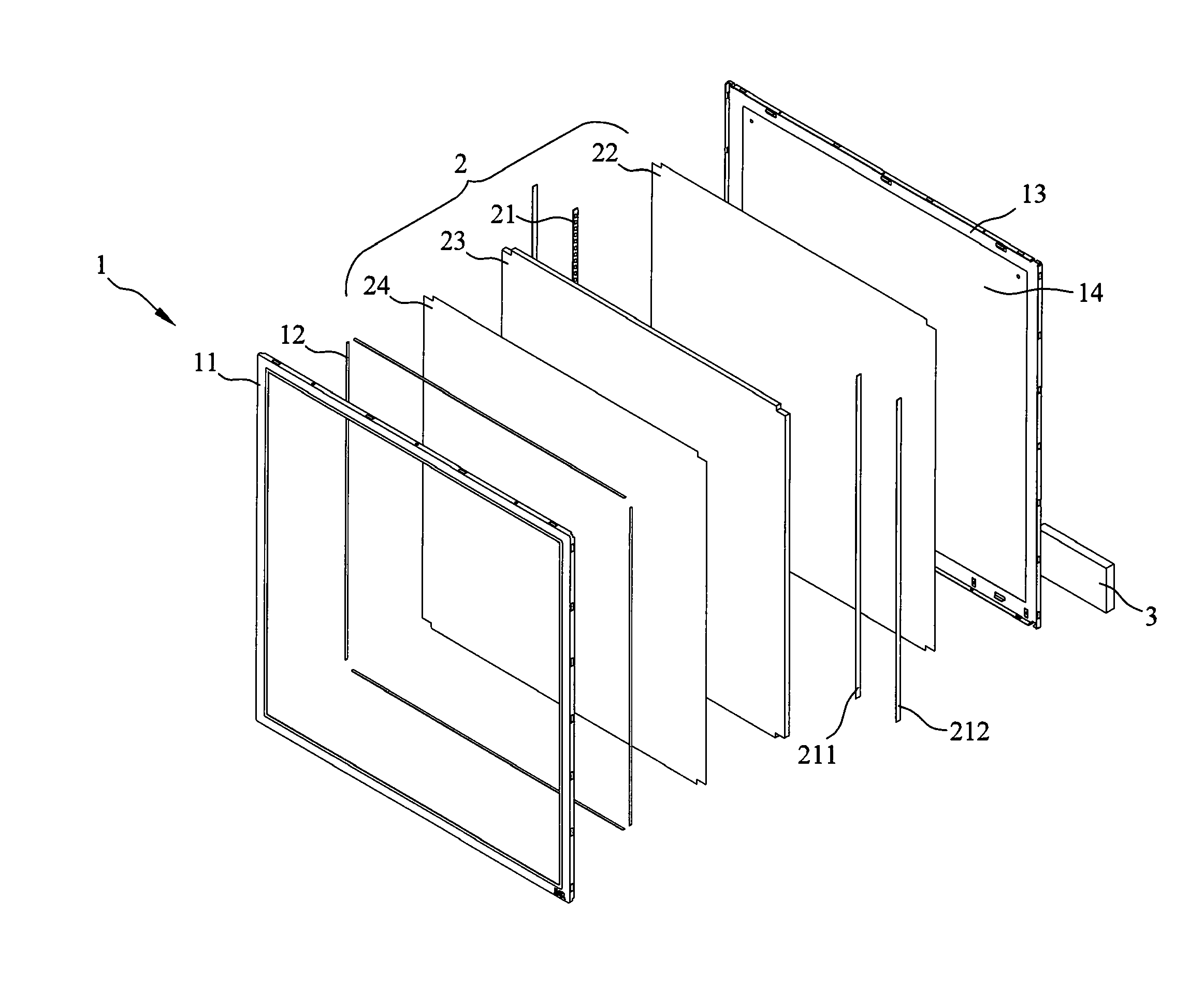
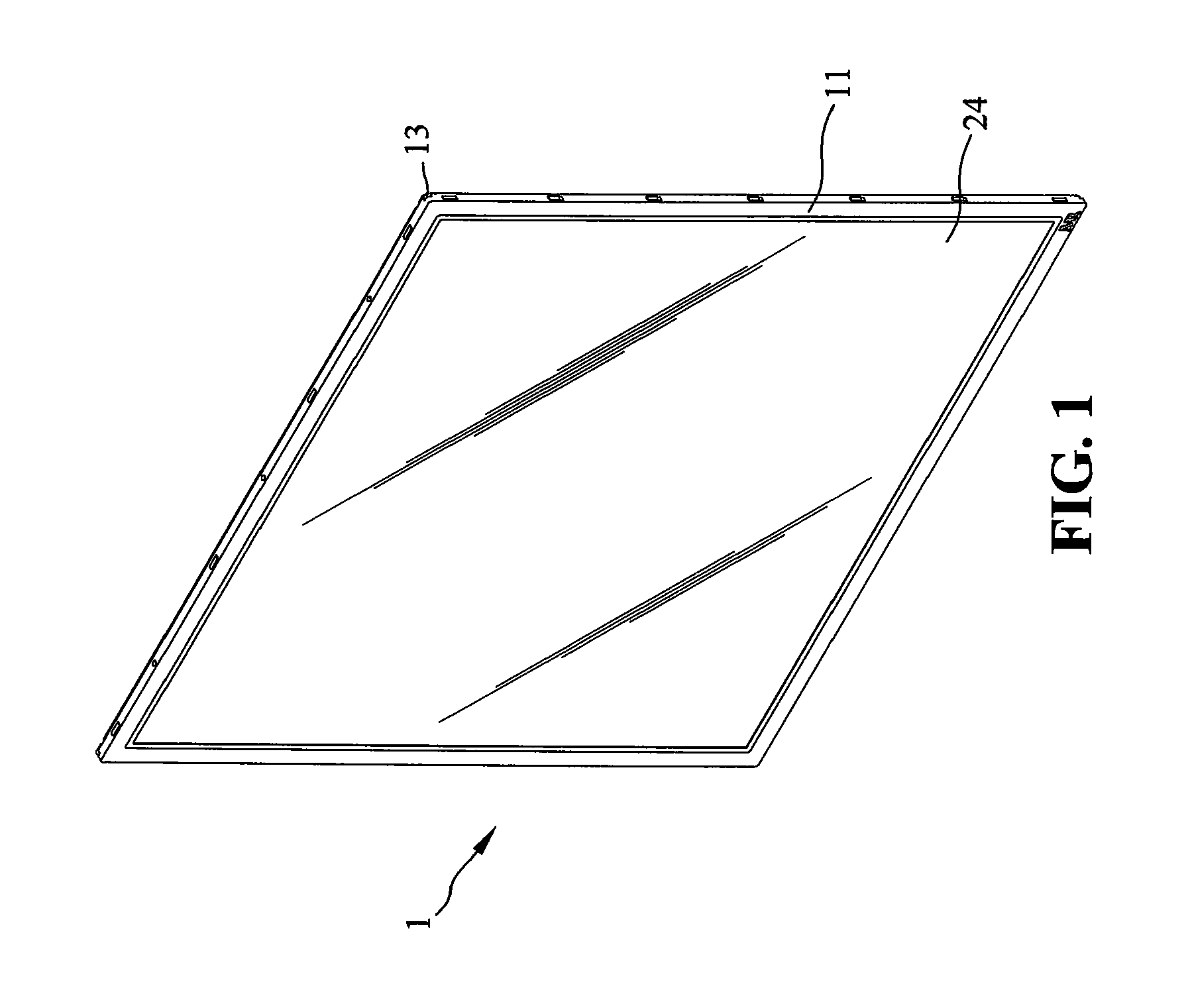
[0019]FIG. 1 is a perspective view of a ceiling mount LED lamp according to an embodiment of the present invention. FIG. 2 is an exploded view of the ceiling mount LED lamp according to an embodiment of the present invention. FIG. 3 is a cross-sectional view of the ceiling mount LED lamp according to an embodiment of the present invention.

[0020]Referring to FIGS. 1 through 3, the ceiling mount LED lamp includes a securing unit 1, and a lighting unit 2.

[0021]The securing unit 1 includes a frame body 11, a back plate 13, a top plate 14, and a plurality of holding strips 12. The back plate 13 is positioned at an opposite side of the frame body 11. The top plate 14 is positioned on the ...


PUM


Abstract

A ceiling mount LED lamp is provided. The ceiling mount LED lamp includes a securing unit, and a lighting unit. The securing unit includes a frame body, a back plate, a top plate, and a plurality of holding strips. The back plate is positioned at an opposite side of the frame body. The top plate is positioned on the back plate. The holding strips are provided at periphery inner sides of the securing unit. The holding strips have a U-shaped cross-section. The lighting unit is positioned between the frame body and the back plate of the securing unit. The lighting unit includes a reflective sheet, at least one circuit board, a plurality of LED units, a light guide plate, and a diffusion sheet. The ceiling mount LED lamp has a simple structure and can be conveniently assembled and disassembled. Further, it is cheap and suitable for mass production.

Description

BACKGROUND OF THE INVENTION[0001]1. Field of the Invention[0002]The present invention relates generally to a lamp, and more particularly, to an LED lamp adapted to be mounted on a ceiling.[0003]2. The Prior Arts[0004]Currently, luminaries mounted on ceilings are often used in home or offices. Such luminaries typically include chandeliers and ceiling mount fluorescent lamps. Generally, a typical chandelier often occupies a large space. When such a chandelier is provided in a home with a 2.7 m floor height, the space may be looked crowd and discordant. As to office used lamps, in most circumstances, ceiling mount fluorescent lamps are selected. A typical ceiling mount fluorescent lamp adapted for office use is a fluorescent lamp tube secured in a frame. Specifically, the frame is a flat metal-made π-shaped structure. The fluorescent lamp tube is secured inside the space defined in the frame, and a rectifier is secured on a backside of the frame or inside the space of the frame. Both o...

Claims


Application Information

Patent Timeline
IPC IPC(8): F21V7/22
CPCF21S8/04F21Y2101/02F21Y2103/003G02B6/0091G02B6/0073G02B6/0083G02B6/0085G02B6/0068F21Y2103/10F21Y2115/10
Inventor CHEN, CHIH-MING
Owner MAXRAY OPTICAL TECH
Learn More