
Method and device for measuring electron diffraction of a sample

Active Publication Date: 2011-03-03
MAX PLANCK GESELLSCHAFT ZUR FOERDERUNG DER WISSENSCHAFTEN EV
View PDF3 Cites 27 Cited by
  • Summary
  • Abstract
  • Description
  • Claims
  • Application Information

AI Technical Summary

Benefits of technology

[0010]In view of above mentioned problems, it is therefore an objective of the invention, to provide an improved m

Problems solved by technology

This dynamical scattering leads to difficulties in the analysis of measured intensity data for structure determination.
Also, by detecting the intensities of the diffracted beams, information about the phase of the diffracted electron beams is lost.
In electron scattering methods, because of the multiple scattering, the kinematic theory is not generally directly applicable.
Integrating the measured intensities over the various angles of incidence, however, leads to a loss of structural information.
If the angular range exceeds this limit, adjacent reflections overlap in the diffraction pattern and cannot be resolved any more.
Therefore, the structural information which can be obtained with this method is limited.

Method used


Image

  • Method and device for measuring electron diffraction of a sample
  • Method and device for measuring electron diffraction of a sample
  • Method and device for measuring electron diffraction of a sample

Examples


Embodiment Construction

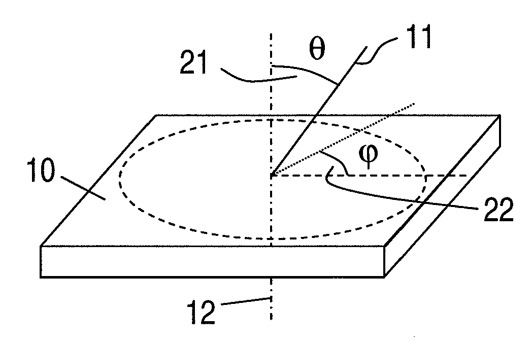
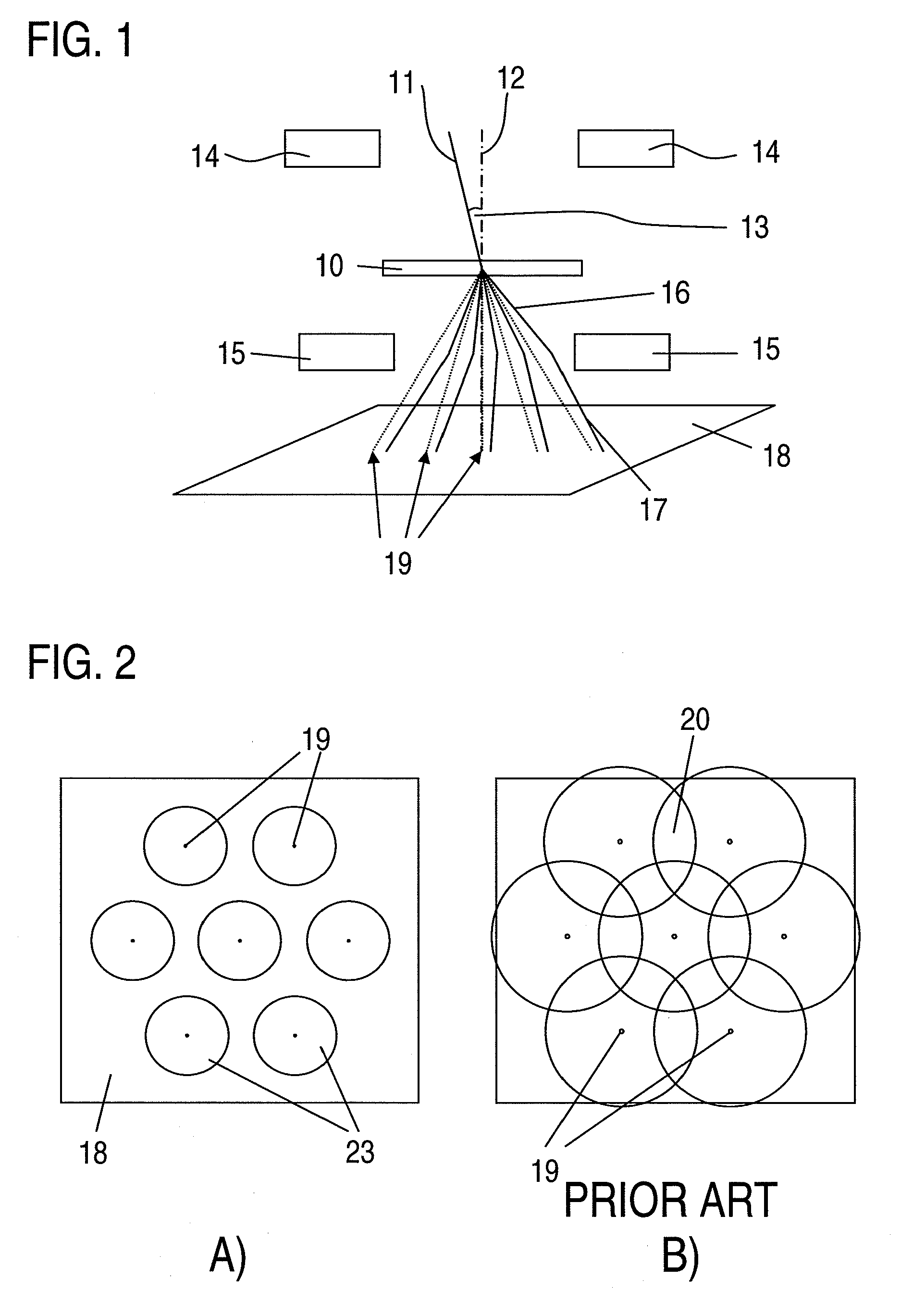
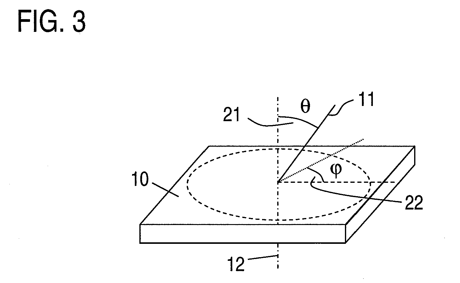
[0021]According to the inventive method, the incident electron beam hits a sample at an angle of incidence relative to a sample axis. The sample axis is an axis having a fixed orientation with respect to the sample. The sample axis can for example be a surface normal to a slide-shaped sample. Preferably, the sample axis is collinear with an optical axis of the experimental setup, e.g., a transmission electron microscope. The angle of incidence with respect to the sample axis comprises two components, the inclination angle θ and the azimuth angle φ as illustrated in FIG. 3. The inclination angle θ is preferably larger than 0.

[0022]A part of the electron beam illuminating the sample is transmitted through the sample undiffracted and at least part of the electron beam is diffracted by the atomic structure of the sample. Accordingly, the electron beam transmitted through the sample comprises undiffracted and diffracted beams which emanate from the sample under various scattering angles....


PUM


Abstract

The invention relates to a method and a device for measuring electron diffraction of a sample, including the steps of illuminating the sample with an incident electron beam which is deflected from a sample axis to hit the sample at an angle of incidence relative to the sample axis, at least partially subjecting the incident electron beam to diffraction by the sample, subjecting the diffracted and undiffracted electron beams transmitted through the sample to a partial deflection compensation, detecting the intensity of the diffracted and undiffracted electron beams transmitted through the sample in dependency on the angle of incidence and a scattering angle of the diffracted beam. The invention also relates to a computer program for controlling a transmission electron microscope for carrying out the inventive method.

Description

BACKGROUND[0001]1. Field of Invention[0002]The invention relates to a method for measuring electron diffraction of a sample by transmission. The invention further relates to a device for deflecting an electron beam incident on a sample and diffracted and undiffracted electron beams transmitted through the sample.[0003]Electron diffraction is a well known method in the field of crystallography for obtaining structure information about crystals. In electron diffraction methods an electron beam is directed onto a sample diffracted by the atomic structure of the sample. Depending on the structure of the sample, like a crystal lattice structure, diffraction leads to reflections at distinct scattering angles, including Bragg reflections. The intensities of the diffracted reflections can be detected as a function of the scattering angle. Such measurement of diffracted intensities as a function of the scattering angle will be called a diffraction pattern within this application. From the me...

Claims


Application Information

Patent Timeline
IPC IPC(8): G01N23/20G21K1/00
CPCG01N23/20058H01J37/26H01J2237/2614H01J2237/1506H01J37/295
Inventor KOCH, CHRISTOPH T.
Owner MAX PLANCK GESELLSCHAFT ZUR FOERDERUNG DER WISSENSCHAFTEN EV
Learn More