
Coupler Draft Gear, Double-Side Operating Coupler and Lower Lockpin Rotation Shaft Assembly

a technology of double-side operation and coupler, which is applied in the direction of railway coupling accessories, railway components, draw gear, etc., can solve the problems of not only improving the operating efficiency of train marshalling, but also ensuring the safety of operators, and the coupling of two cars cannot be successfully coupled together, so as to improve coupling reliability, avoid interference with the use and performance of the coupler, and operate reliably

Active Publication Date: 2011-03-03
CRRC QIQIHAR ROLLING CO LTD +1
View PDF21 Cites 5 Cited by
  • Summary
  • Abstract
  • Description
  • Claims
  • Application Information

AI Technical Summary

Benefits of technology

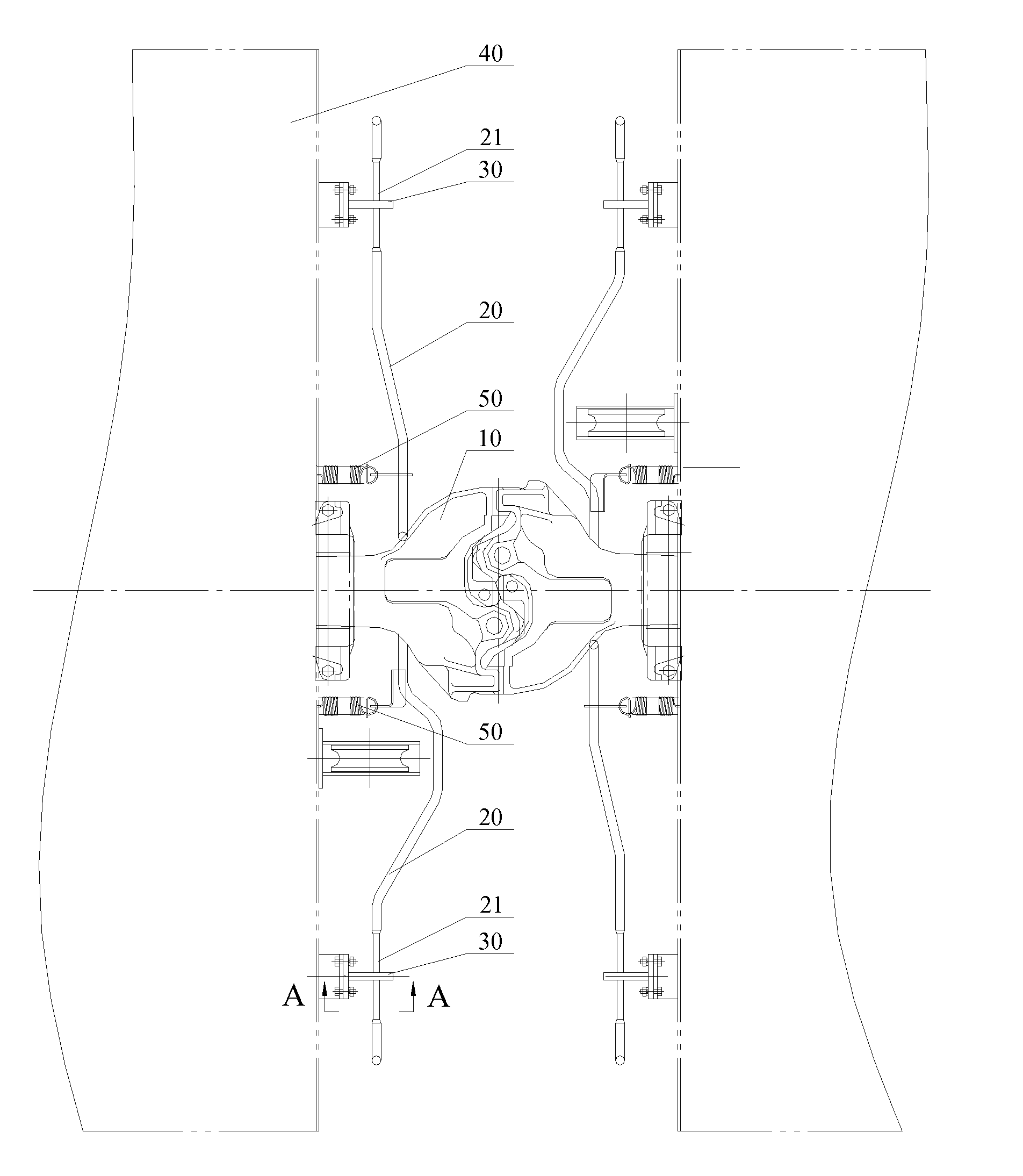
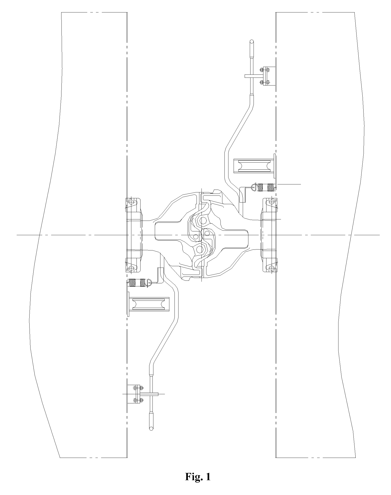
[0012]The coupler draft gear according to the present invention includes a coupler, coupler lifting bar coupled with coupler lifting bar hole of the coupler, and coupler lifting bar seat cooperated with the coupler lifting bar. The coupler lifting bar seat has a keyhole-shaped through hole; the coupler lifting bar is inserted in the keyhole-shaped through hole of the coupler lifting bar seat, the coupler lifting bar has a restrained segment at a fitted portion of the coupler lifting bar with the coupler lifting bar seat, the restrained segment of the coupler lifting bar has a rectangular cross-section matching with a rectangular cross-section at a lower portion of the keyhole-shaped through hole. The coupler adopts the double-side operating coupler as described above. It is provided two coupler lifting bar seats, which are fixedly disposed on a car body at both sides of the coupler, respectively. It is provided two coupler lifting bars, and coupler heads of the two coupler lifting bars are inserted through the keyhole-shaped through holes of the two coupler lifting bar seats and then coupled with the first coupler lifting bar hole and the second coupler lifting bar hole of the double-side operating coupler. There is a gap between the restrained segment of the coupler lifting bar and walls of the rectangular hole of the keyhole-shaped through hole of the coupler lifting bar seat. The fit between the keyhole-shaped hole in the coupler lifting bar seat and the restrained segment of the coupler lifting bar may prevent the coupler lifting bar from swaying back and forth when the train vibrates in longitudinal direction, thus avoiding the fact that the coupler is unlocked due to mistake operation, leading to a train separating accident.
[0016]The lower lockpin rotation shaft assembly according to the present invention includes two main components, i.e., a lower lockpin rotation shaft body and a lower lockpin rotation shaft bush. The structure and functions of the lower lockpin rotation shaft body are basically same as that of lower lockpin rotation shaft in the prior art. The outer end portion of the lower lockpin rotation shaft body has a coupler lifting bar hole, i.e., the first coupler lifting bar hole. The outer end portion of the lower lockpin rotation shaft bush has a coupler lifting bar hole, i.e., the second coupler lifting bar hole. During assembling, the inner end portion of the lower lockpin rotation shaft body protrudes through a hole in the coupler body and then is fixedly connected to the inner end portion of the lower lockpin rotation shaft bush. The first coupler lifting bar hole and the second coupler lifting bar hole are located at both sides of the coupler body, respectively, such that the operator standing any side of car body may easily and reliably perform the unlock operation to front and rear couplers at connecting end of two cars.
[0018]In the preferred embodiment of the lower lockpin rotation shaft assembly according to the present invention, the first coupler lifting bar hole and the second coupler lifting bar hole are opened in an identical direction. Thus, when performing an unlock operation at both sides of car, the rotating angles of them are the same, so as to improve the interchangeability of product, which is applicable to mass production.
[0020]Based on the above description, when any coupler lifting bar according to the present invention is manipulated to unlock the coupler, the problem of interference with each other will not occur, and the use and performance of the coupler isn't affected. Thus, the coupler of the present invention may be operated reliably. Furthermore, the coupler lifting bar seats having keyhole-shaped hole are provided for the coupler lifting bars at both sides to achieve a better coupling reliability between the couplers.
[0021]In the preferred embodiment of the double-side operating coupler of the present invention, a tension spring is provided for each coupler lifting bar. The tension spring is disposed between the coupler lifting bar and the car body. When any coupler lifting bar is rotated to unlock the coupler, corresponding tension spring is stretched and deformed and thus stores the energy of deformation. After an unlock operation, the coupler lifting bar is quickly returned by the tension spring, so as to come into pre-unlock ready state, which further improves the operability of the present invention.

Problems solved by technology

When a coupler is in the locked state, a coupler knuckle lock stops a coupler knuckle from being opened, and coupled cars cannot be separated spontaneously.
In this way, it can not only improve the operating efficiency of train marshalling, but also ensure the safety of operator.
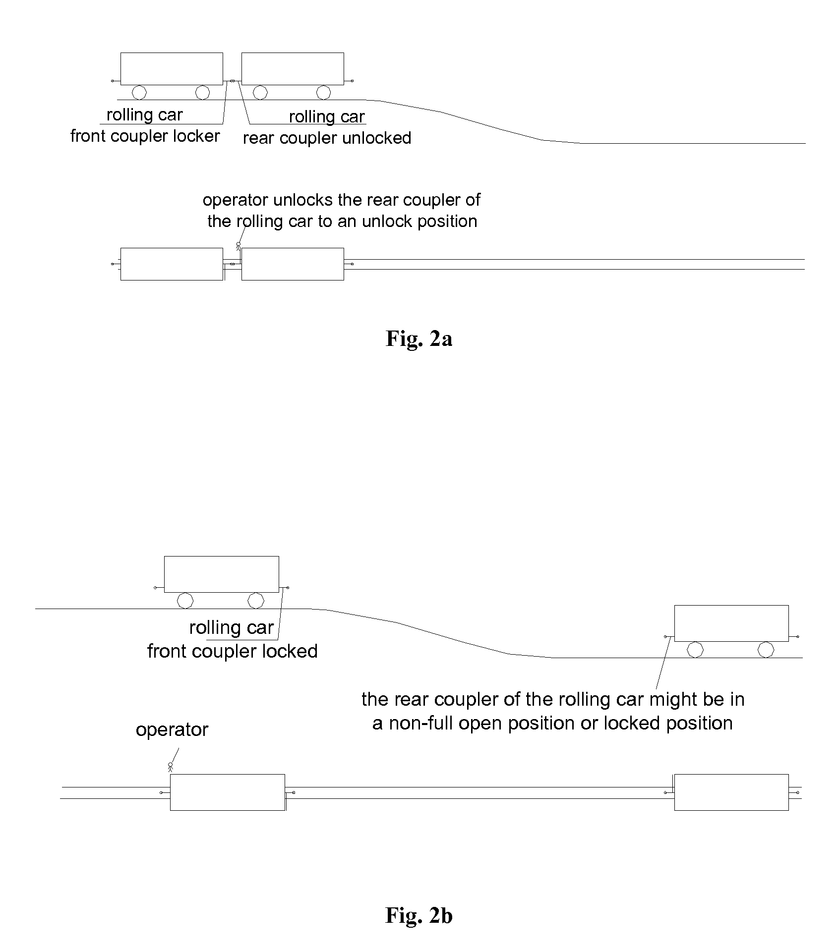
Therefore, after the subsequent rolling car rolls downwardly, the two cars can not be successfully coupled together.
Accordingly, the success ratio of coupling in marshalling is decreased, which may affect the operating efficiency in marshalling and also may directly or indirectly affect the safety of operator in operating.

Method used


Image

  • Coupler Draft Gear, Double-Side Operating Coupler and Lower Lockpin Rotation Shaft Assembly
  • Coupler Draft Gear, Double-Side Operating Coupler and Lower Lockpin Rotation Shaft Assembly
  • Coupler Draft Gear, Double-Side Operating Coupler and Lower Lockpin Rotation Shaft Assembly

Examples


Embodiment Construction

[0031]The object of the present invention is to provide a lower lockpin rotation shaft assembly with two coupler lifting bar hole which are respectively located at two sides of a coupler body after assembling with the coupler body so as to facilitate engaging with coupler lifting bars at two sides, which may achieve a reliable coupler unlock operation from two sides, so as to be applicable to many operating conditions such as hump shunting.

[0032]Hereinafter, the present embodiment will be specifically described with reference to the drawings in the specification.

[0033]Referring to FIG. 3, a schematic structural view after assembling the lower lockpin rotation shaft assembly and the coupler body of the present invention together is shown.

[0034]As shown in FIG. 3, the lower lockpin rotation shaft assembly mainly consists of a lower lockpin rotation shaft body 11 and a lower lockpin rotation shaft bush 12. In order to explain the structure of the lower lockpin rotation shaft body 11 an...


PUM


Abstract

A lower lockpin rotation shaft assembly includes a lower lockpin rotation shaft body, an outer end portion thereof having a first coupler lifting bar hole, an intermediate portion thereof having a connecting key; and a lower lockpin rotation shaft bush, an outer end portion of the lower lockpin rotation shaft bush having a second coupler lifting bar hole, and an inner end portion of the lower lockpin rotation shaft bush being operatively connected to an inner end portion of the lower lockpin rotation shaft body. Further, the present invention further provides a double-side operating coupler and a coupler draft gear having the above lower lockpin rotation shaft assembly. The coupler draft gear further includes two coupler lifting bars and two coupler lifting bar seats. Each of the coupler lifting bars is inserted in a keyhole-shaped through hole of corresponding coupler lifting bar seat, and the coupler lifting bar has a restrained segment at a fitted portion of the coupler lifting bar with the coupler lifting bar seat. Coupler heads of the two coupler lifting bar are inserted through the keyhole-shaped through holes of the two coupler lifting bar seats and then coupled with the first coupler lifting bar hole and the second coupler lifting bar hole of the double-side operating coupler. There is a gap between the restrained segment of each coupler lifting bar and walls of the rectangular hole of the keyhole-shaped through hole.

Description

[0001]The present application claims benefit of the priority to CN application No. 200910006055.2 titled “COUPLER DRAFT GEAR, DOUBLE-SIDE OPERATING COUPLER AND LOWER LOCKPIN ROTATION SHAFT ASSEMBLY”, filed with the Chinese State Intellectual Property Office on Jan. 22, 2009. The entire disclosure thereof is incorporated herein by reference.FIELD OF THE INVENTION[0002]The present invention relates to coupling technology between carriages of railcar, and more specifically to a coupler draft gear, a double-side operating coupler and a lower lockpin rotation shaft assembly.BACKGROUND OF THE INVENTION[0003]The coupler is one of important parts of a railcar, and has a standard connecting contour. It is mainly used to ensure the coupling between cars and achieve operations of train marshalling and car drafting.[0004]Typically, conventional train coupler will be operated in three operating states, i.e., locked state, unlock state and full open state. When a coupler is in the locked state, a...

Claims


Application Information

Patent Timeline
Patent Type & Authority Applications(United States)
IPC IPC(8): B61G3/08B61G3/06B61G3/04B61G9/20
CPCB61G7/02
Inventor MENG, QINGMINJIANG, YANYU, YUEBINCUI, YINGJUNCHEN, LONGWANG, JUNSONGSUN, HONGJI
Owner CRRC QIQIHAR ROLLING CO LTD
Learn More