
Vertical lift arm device

a vertical lift and arm technology, applied in lifting devices, cranes, constructions, etc., can solve problems such as potential safety concerns, difficult access to engine components, and complicated pivoting of the operator compartment, and achieve the effects of easy opening or pivoting, improving safety, and improving safety

Active Publication Date: 2011-02-03
CNH IND AMERICA LLC
View PDF11 Cites 2 Cited by
  • Summary
  • Abstract
  • Description
  • Claims
  • Application Information

AI Technical Summary

Benefits of technology

[0006]One aspect of the invention is directed to a skid steer loader having an operator compartment attached to a frame. Lift assemblies are movably mounted to the frame and are movable between a retracted position and an extended position. Joining plates are rigidly coupled to the lift assemblies. First links are pivotally coupled to the frame proximate a back of the operator compartment and are pivotally coupled to the joining plates. Second links are pivotally coupled to the frame proximate a back of the operator compartment and are pivotally coupled to the joining plates. As the lift assemblies are moved between the retracted position and the extended position, the joining plates, the first links and the second links are positioned behind the operator compartment to provide a better field of vision for the operator.
[0009]In one embodiment of the skid steer loader described herein, the operator will have a generally unobstructed field of view of the work area and surroundings regardless of the position of the lift assemblies or, thereby providing for ease of operation and increased safety. In addition, the operator compartment may be easily opened or pivoted to allow for better service access to parts of the engine and other components. In addition, as the first links, the second links and the lift actuators may be mounted on the frame at the rear of the skid steer loader, the operator compartment can easily be pivoted forward whether the lift assemblies are lowered or raised or in any position therebetween. The positioning of the pivot points on the frame, where substantial structure must be provided to strengthen the base regardless of the presence of the pivot points, obviates the need to provide additional structure to support the lift assembly. Also, the placement of the lift actuator is such that the full lift height of the bucket is achieved with a shorter actuator than is possible with some prior-art designs.

Problems solved by technology

Four-bar linkage designs generally provide a linkage that is coupled to the operator compartment, complicating the pivoting of the operator compartment and making access to engine components difficult.
Radial lift skid steer loaders generally obstruct the operator's view, thereby creating potential safety concerns.

Method used


Image

  • Vertical lift arm device
  • Vertical lift arm device
  • Vertical lift arm device

Examples


first embodiment

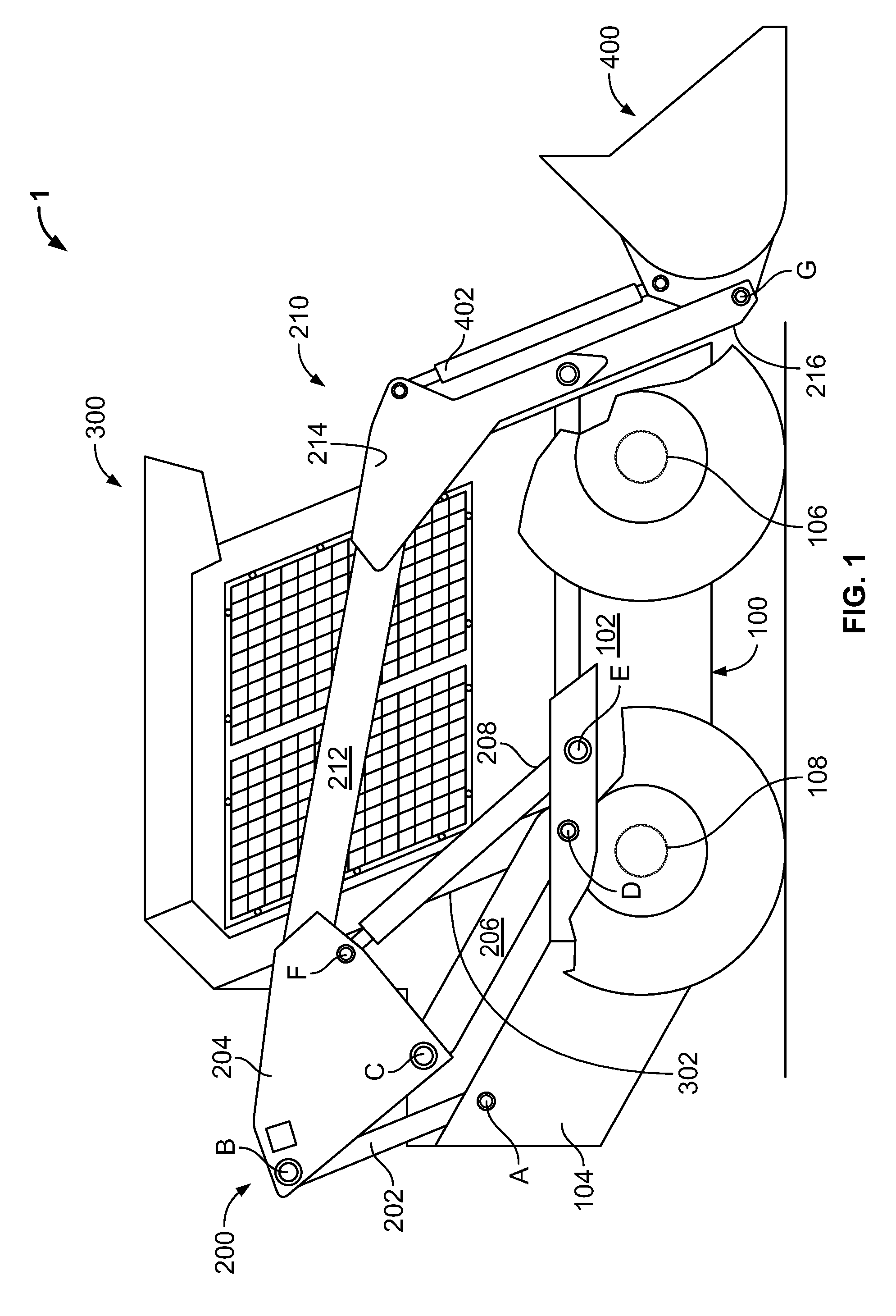
[0020]As shown in FIG. 1, a skid steer loader 1 includes a frame 100. An operator compartment 300 is attached to the top of the frame 100. The frame 100 includes a base 102, on which a plurality of wheels or a pair of tracks are rotatably mounted on front and rear axles 106, 108 or the like, and a rearward extending engine-mounting portion 104 that houses drive components (not shown) such as an engine and hydraulic pumps. Alternative or additional drive components such as chains, hydraulic motors, a transmission, drive shafts, electric motors or the like may be housed within the base. The drive components provide motive power to the skid steer loader in addition to driving a hydraulic pump to provide pressurized fluid for hydraulic actuators 208 and 402. The implement actuator 402 actuates a tipping motion of an implement, such as a bucket 400, and the hydraulic lift actuator 208 extends and retracts a lift assembly.

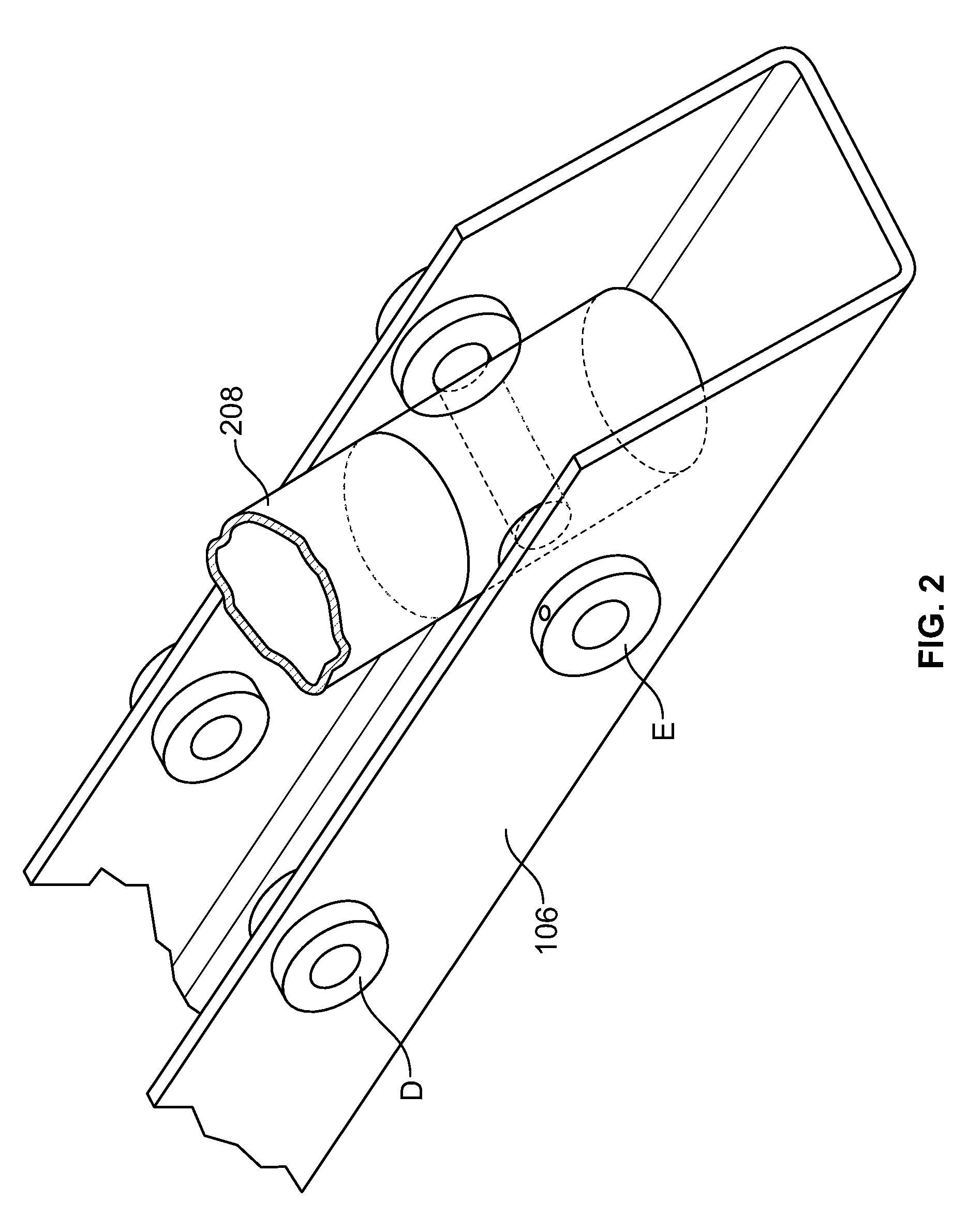
[0021]The frame 100 includes a plurality of pivot points A, D, E. ...

second embodiment

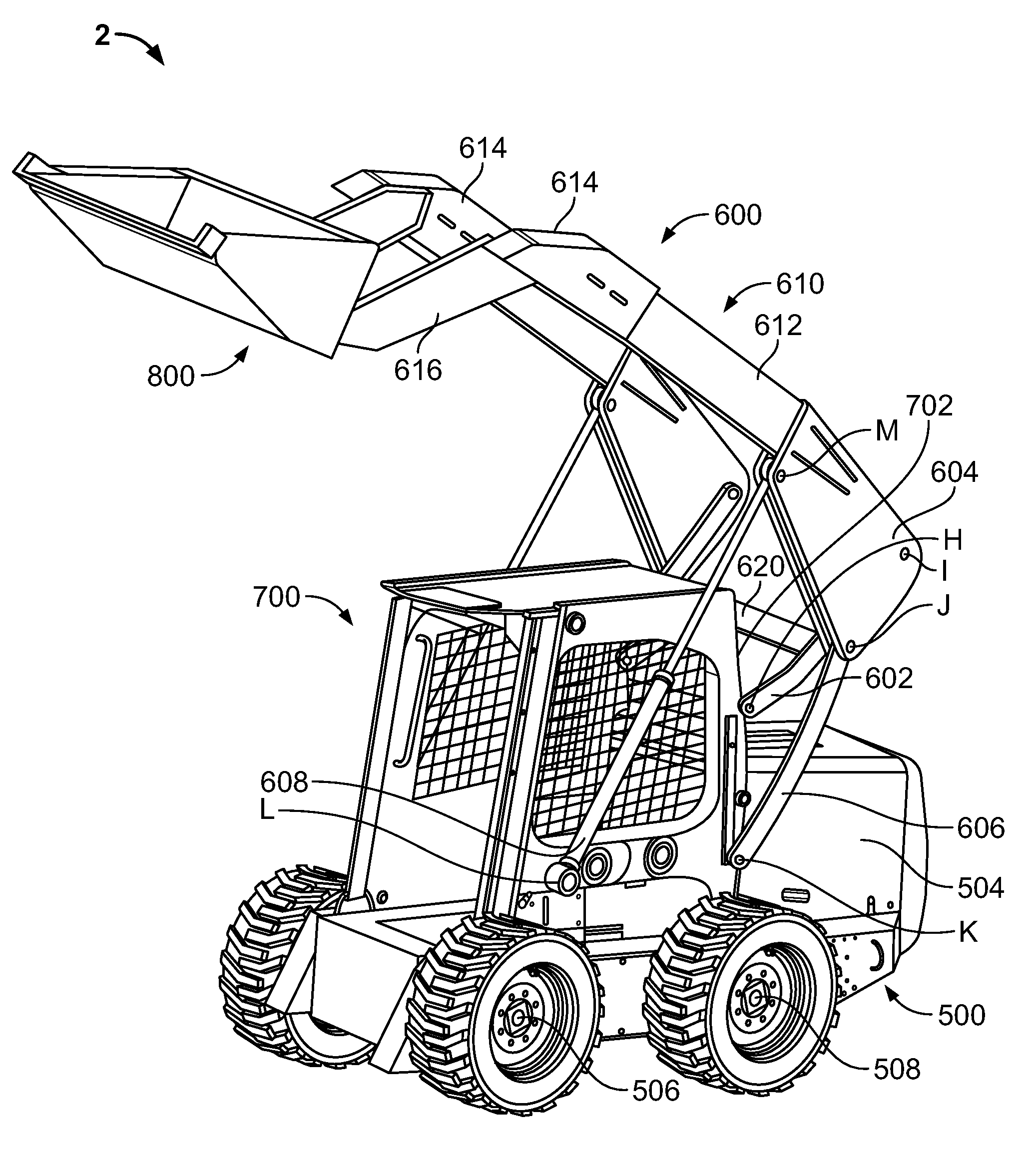
[0037]As shown in FIGS. 8 through 10, a skid steer loader 2, includes a frame 500. An operator compartment 700 is attached to the top of the frame. The frame 500 includes a base 502, on which a plurality of wheels or a pair of tracks are rotatably mounted on front and rear axle 506, 508 or the like, and a rearward extending engine-mounting portion 504 that houses drive components such as those previously described, or additional drive components such as chains or hydraulic motors. The drive components provide motive power to the skid steer loader, in addition to driving hydraulic pumps to provide pressurized fluid for hydraulic implement actuators which move a bucket 800 and extend and retract lift assemblies 600.

[0038]The frame 500 includes a plurality of pivot points H, K, L. In the embodiment shown in FIG. 10, the pivots points H, K, L are generally disposed with pivot points L mounted on the frame 500 above the front axle 506 and pivot points H, K mounted on the frame 500 above...


PUM


Abstract

A skid steer loader having an operator compartment attached to a frame. Lift assemblies are movably mounted to the frame and are movable between a retracted position and an extended position. As the lift assemblies are moved between the retracted position and the extended position, joining plates, first links and second links are positioned behind the operator compartment to provide a better field of vision for the operator.

Description

FIELD OF THE INVENTION[0001]The present invention relates to a loader arm device, and in particular, to a vertical lift arm device for use on a skid steer loader.BACKGROUND OF THE INVENTION[0002]Skid steer loaders are compact vehicles useful on farms and construction sites to maneuver in tight spaces and transport heavy or bulky items. Typical skid steer loaders include a boom that can be raised and lowered and a bucket attached to the end of the boom whereby items can be lifted off the ground, transported, and placed back on the ground or dumped into a receptacle with high walls, such as a dump truck. The skid steer loaders are generally considered to have either a radial lift load-arm, in which the boom has a single pivot point, or a vertical lift load-arm, in which a four-bar linkage is used to raise and lower the boom.[0003]Operators want to be able to service their skid steer loader easily. The operator compartment of a skid steer loader typically pivots on the frame to reveal ...

Claims


Application Information

Patent Timeline
IPC IPC(8): E02F9/00
CPCE02F3/3414E02F3/3405
Inventor ENGLAND, MARK L.REYES, DAVIDPLANTE, SEANWAGNER, ED
Owner CNH IND AMERICA LLC
Learn More