
Method for validating features in a direct modeling paradigm

Active Publication Date: 2011-02-03
AUTODESK INC
View PDF9 Cites 30 Cited by
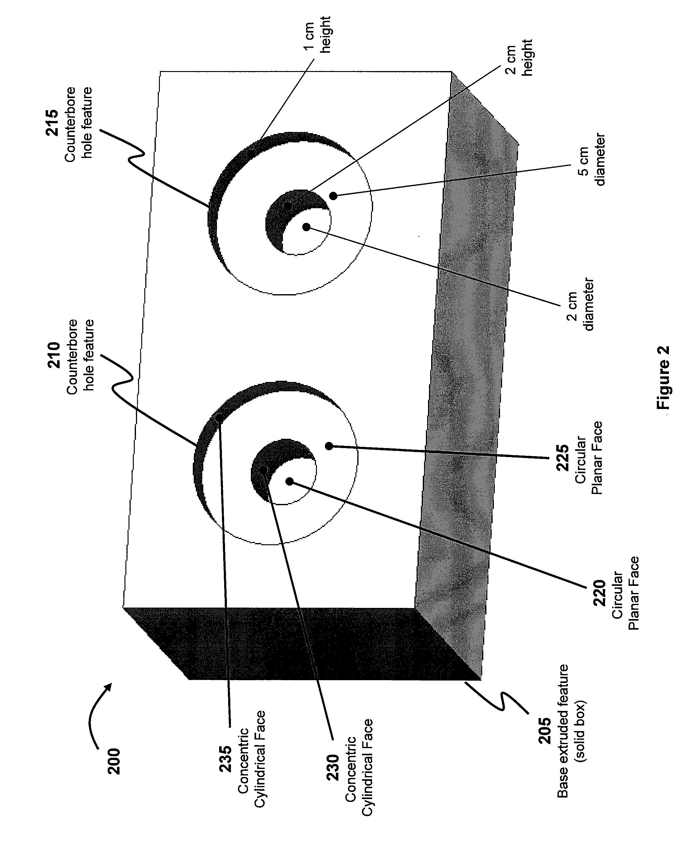
  • Summary
  • Abstract
  • Description
  • Claims
  • Application Information

AI Technical Summary

Benefits of technology

[0008]One or more embodiments of the present invention provide a CAD system that enables a designer to quickly and freely make modifications to the geometry of a model without consuming significant computational resources, similar to traditional explicit modeling, but that also preserves the design intent of the original design by associating features with the shapes in the geometry, similar to traditional parametric feature-based modeling. In particular, a model generated by a CAD system according to one or more embodiments of the present invention comprises a plurality of data objects wherein each data object represents a design feature. Furthermore, each data object is defined by a plurality of geometric faces and is associated with set of rules relating to the position of the geometric faces in relation to one another.
[0010]One advantage of the disclosed method is that a designer is able to maintain a level of editing freedom that is similar to traditional direct modeling approaches, but still preserve design intent through the use of features in a manner similar to parametric feature-based modeling approached.

Problems solved by technology

However, providing such capability also results in added complexity from a designer perspective.
A lack of such understanding of the history can lead to “brittle” designs that fail during regeneration of the model because edits made by a designer in the history cannot be reconciled with subsequent operations in the history.
Additionally, parametric feature based modeling also requires significant computational resources due to the need to store history and regenerate geometries based on the re-execution of historical operations.
As such, editing models using parametric feature based modeling can often be time-consuming.
As such, when a designer makes a modification to the geometry of a model, the design intent of the original model can be easily destroyed and the mechanical soundness of the model be compromised as a result of the modification.

Method used


Image

  • Method for validating features in a direct modeling paradigm
  • Method for validating features in a direct modeling paradigm
  • Method for validating features in a direct modeling paradigm

Examples


Embodiment Construction

[0015]FIG. 1 illustrates a computer system configured to implement one or more embodiments of the present invention. Computer system 100 is a general purpose computer such as, for example, a desktop computer, laptop computer or any other computer. Computer system 100 includes a host computer 105 with a central processing unit (CPU) 110, a random access memory (RAM) 115 and an internal hard disk drive 120. The CPU 110, RAM 115 and internal hard disk driver 120 interact through a system bus 125 that also enables the host computer 100 to interact a display device, such as monitor 130, and input devices, such as keyboard 135 and mouse 140. A CAD system 145 (i.e., written in software) is loaded into RAM 115 and stores CAD files 150 in internal hard driver 120. Such CAD files 150, for example, store CAD models designed by a designer through the use of CAD system 145. It should be recognized that FIG. 1 and the foregoing description are simplified representations of a real general purposes...


PUM


Abstract

A CAD system enables a designer to freely modify a model of a design without regenerating a history of the model, as in traditional parametric feature based modeling. The CAD system automatically determines whether the modifications to the model invalidate current features associated with the model and whether the modifications create new features that should be added to the model. Such a CAD system enables a designer to quickly edit designs and simultaneously preserve design intent without requiring the significant computational resources of historical based approaches that regenerate a geometry upon every edit made by a designer.

Description

BACKGROUND OF THE INVENTION[0001]1. Field of the Invention[0002]The present invention generally relates to computer aided design (“CAD”) and, more specifically, to identifying features in CAD models.[0003]2. Description of the Related Art[0004]Current CAD systems typically utilize parametric feature based modeling to create computer-based models for designs. In parametric feature based modeling, a model for a design can be generally thought of as a collection of features.[0005]A feature is a data object representing a form or a shape (such as a hole, slot, extrusion, boss, pocket, etc.) that may be incorporated into a particular model. The data object describes the mechanical properties of the feature by including shape information that generally defines the geometric requirements for the feature (e.g., how many planar faces, cylindrical faces, etc.), position information (e.g., what positional constraints are imposed on the geometric faces of the feature in relation to one another,...

Claims


Application Information

Patent Timeline
IPC IPC(8): G06T17/00
CPCG06T19/20G06F30/17
Inventor SCHNEIDER, KEVINVORA, RAHULSTRATER, JEFFREY THOMASYEH, SHU-CHIEH
Owner AUTODESK INC
Learn More