
Incubator comprising a shaking device

a technology of shaking device and incubator, which is applied in the field of incubators, can solve the problems of affecting the climate in the incubation chamber, the sealing between the incubation chamber, and the wear of the bellows of this typ

Active Publication Date: 2010-12-30
SARTORIUS STEDIM BIOTECH GMBH
View PDF10 Cites 34 Cited by
  • Summary
  • Abstract
  • Description
  • Claims
  • Application Information

AI Technical Summary

Benefits of technology

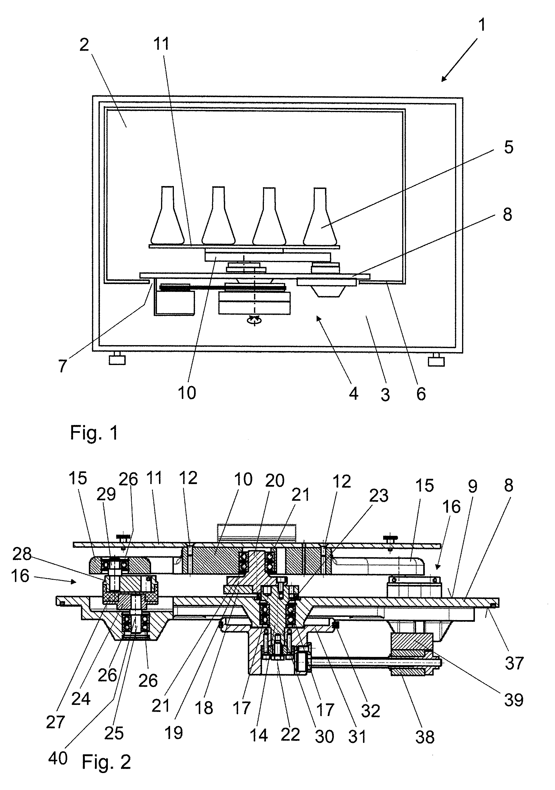
[0012]By arranging the motor on the outer face of the base plate and arranging the drive arm with the movable shaking table on the inner face of the base plate, it is possible to mount the drive shaft on the base plate rotatably but fixedly, i.e. without superposed sideways movements. It is thus possible to dispense with a bellows and to achieve an effective seal of the incubation chamber relative to the device chamber by way of the base plate. It is thereby possible in practice to avoid heat from the device chamber entering the incubation chamber. It is also possible to avoid moisture from the incubation chamber entering the device chamber. The shaking movements of the shaking table movable in a horizontal plane are generated on the inner face of the base plate directed toward the incubation chamber. The shaking device can be fitted relatively simply and inexpensive as an insert device by fixing the base plate between incubation chamber and device chamber.
[0016]According to another preferred embodiment of the invention, a seal is arranged between the drive shaft and the base plate. The seal is designed, for example, as a low-friction lip seal or labyrinth seal. This avoids moisture from the incubation chamber entering the device chamber.

Problems solved by technology

A disadvantage of the above is that, because of the shaking movement, the seal between incubation chamber and device chamber can be provided only via an elastic bellows.
Bellows of this kind are susceptible to wear and can, for example, tear, such that moisture from the incubation chamber can enter the device chamber.
Moreover, the heat generated in the device chamber, particularly by the motor of the shaking device, can affect the climate in the incubation chamber by way of the bellows.
A disadvantage of this known device is that the heat given off by the device can affect the climate in the incubation chamber in an undesirable manner.
The coolant circuit is not needed for the culturing, and to provide it simply to take up the heat given off by the shaking device is therefore relatively expensive and complicated.

Method used


Image

  • Incubator comprising a shaking device
  • Incubator comprising a shaking device
  • Incubator comprising a shaking device

Examples


Embodiment Construction

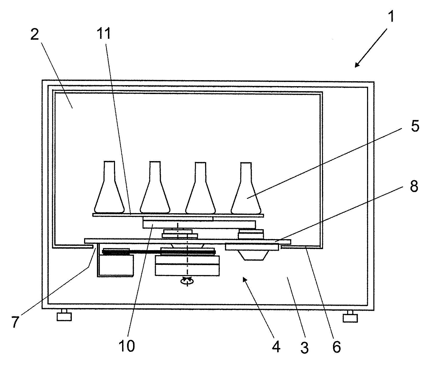
[0022]An incubator 1 basically comprises an incubation chamber 2, a device chamber 3 and a shaking device 4.

[0023]The incubation chamber 2, in which cell cultures placed in receptacles 5 are cultivated, is arranged in the incubator 1. For the purpose of cultivation, the temperature and humidity in the incubation chamber 2 can be adjusted. A device chamber 3 is arranged vertically below the incubation chamber 2. A floor 6 of the incubation chamber 2 has, toward the device chamber 3, a floor opening 7 that serves as a connection to the device chamber 3.

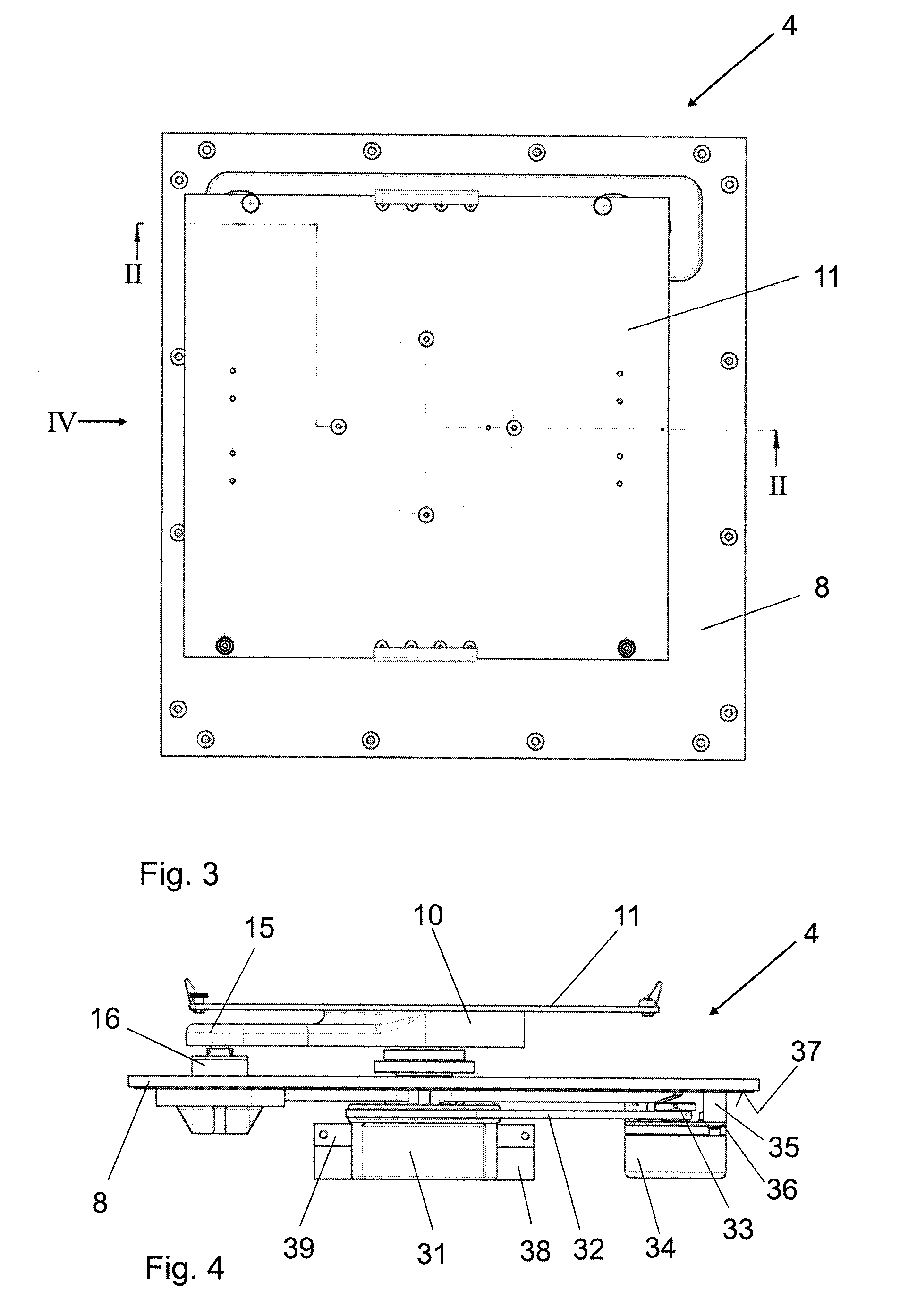
[0024]The shaking device 4 is designed as an insert device which can be fitted into the floor opening 7 in such a way that the base plate 8 of the device seals off the incubation chamber 2 relative to the device chamber 3. On its inner face 9 directed toward the incubation chamber 2, the base plate 8 has a shaking table 11 that can be moved in a horizontal plane by a drive arm 10. The shaking table 11 is connected securely to the drive ...


PUM


Abstract

An incubator (1) with an incubation chamber (2), a shaking device (4) which can be driven by a drive unit and which is used to shake receptacles (5) that can be placed in the incubation chamber (2) and that contain cell cultures, and a device chamber (3) which adjoins the incubation chamber (2) and which accommodates at least parts of the shaking device (4) protruding into the incubation chamber (2), wherein the shaking device (4) has a base plate (8) which seals off the incubation chamber (2) relative to the device chamber (4) and which, on its inner face (9) directed toward the incubation chamber (2), has a shaking table (11) that can be moved in a horizontal plane by a drive arm (10), wherein a motor (34) is arranged on the outer face (37) of the base plate (8) directed away from the inner face (9), which motor (34) drives a drive shaft (14) that is rotatably mounted in the base plate (8) and that is operatively connected to the drive arm (10).

Description

BACKGROUND OF THE INVENTION[0001]1. Field of the Invention[0002]The invention relates to an incubator with an incubation chamber, a shaking device which can be driven by a drive unit and which is used to shake receptacles that can be placed in the incubation chamber and that contain cell cultures, and a device chamber which adjoins the incubation chamber and which accommodates at least parts of the shaking device protruding into the incubation chamber.[0003]2. Description of the Related Art[0004]Incubators are used to cultivate cell cultures that are arranged in receptacles placed in the incubation chamber. Shaking devices are used in order to achieve better cell growth.[0005]EP 1 626 082 B1 discloses an incubator comprising an incubation chamber at whose lower end a device chamber is arranged. The device chamber accommodates a shaking device for shaking or agitating receptacles that are placed in the incubation chamber and that hold cell cultures. For this purpose, a shaft protrude...

Claims


Application Information

Patent Timeline
IPC IPC(8): C12M1/02
CPCC12M27/16C12M41/14C12M27/00C12M23/50Y10S435/809B01F11/0094B01F11/0014B01F11/0008B01F11/00C12M23/48B01F31/22B01F31/00B01F31/60B01F31/201
Inventor BAUMFALK, REINHARDOBERMANN, STEFANSANDROCK, RAINER
Owner SARTORIUS STEDIM BIOTECH GMBH
Learn More