
Virtual Control Station

a virtual control station and platform technology, applied in the field of virtual control stations, can solve the problems of limiting the number of display systems that can be viewed simultaneously, limiting the size of the display system, and large and heavy control stations

Active Publication Date: 2010-12-30
THE BOEING CO
View PDF25 Cites 53 Cited by
  • Summary
  • Abstract
  • Description
  • Claims
  • Application Information

AI Technical Summary

Benefits of technology

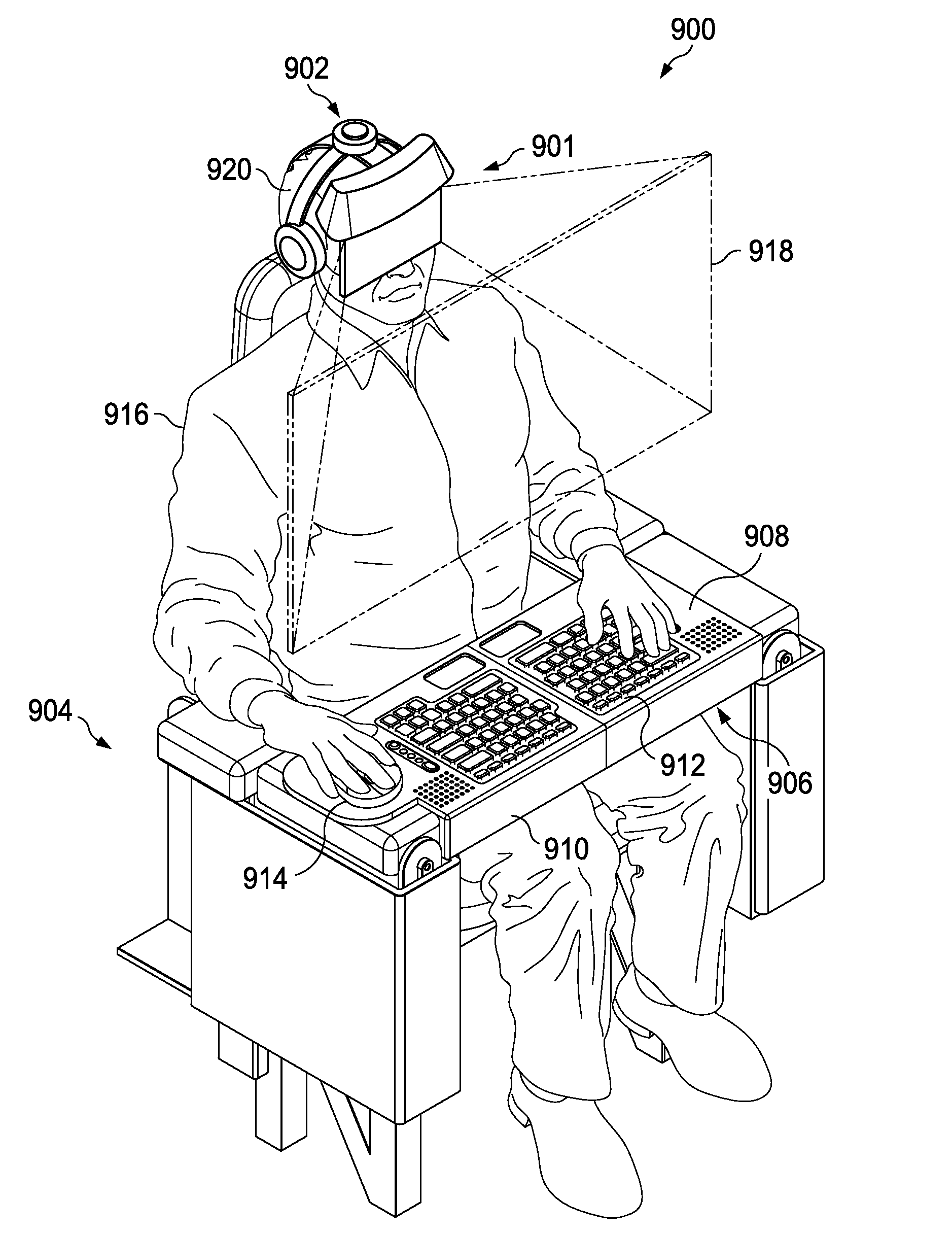
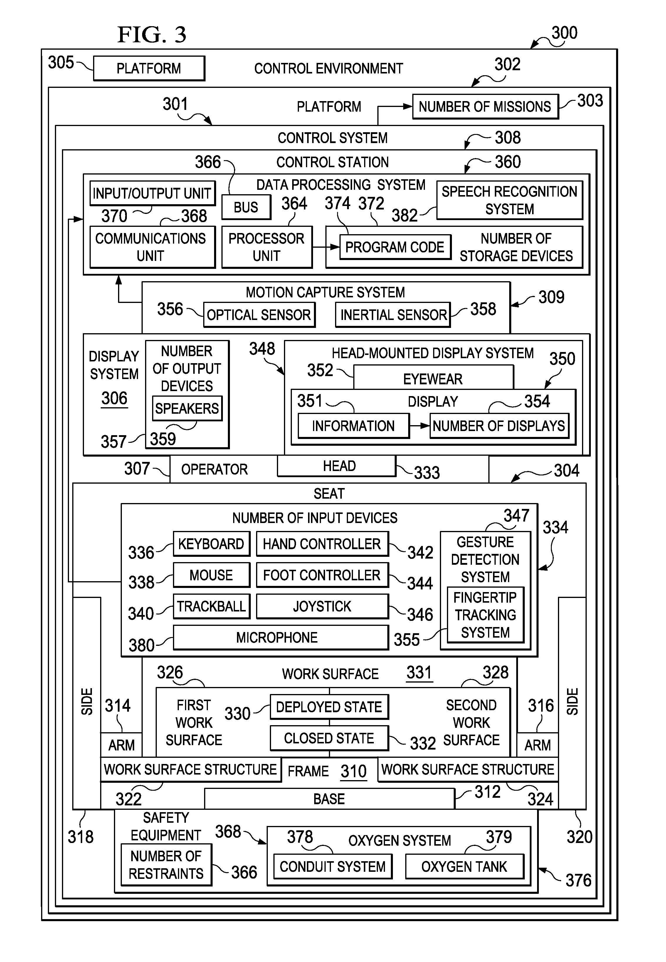
[0012]In another illustrative embodiment, a method is present for performing a mission. Information for a mission is received at a control station. The control station comprises a display system, a motion capture system, a number of user input devices, a seat associated with the number of user input devices, and a processor unit. The display system is configured to be worn on the head of an operator and to pr...

Problems solved by technology

Currently, control stations are large and heavy.
This configuration limits the number of display systems that can be viewed simultaneously.
Also, this configuration limits the size of the display systems.
Mounting the display systems to the structures associated with the platform further decreases floor space in the platform.
The limited number of display systems mounted to the structures of the platform also limits the number of simultaneously accessible user functions that can be managed by an operator at the control station.
Further, existing control stations can limit operator mobility within a control station.
This limit to operator mobility can result in operator fatigue for missions of long duration.
The mobility of an operator may be further limited if the operator is to perform functions at the control station while seated with restraints.
Interactions performed by operators can be limited by currently used control stations.
This type of configuration is not always possible due to safety constraints for the platform.
Operator interactions also may be limited by space constraints.
These space constraints may be caused by the size of current control stations.
Weight also may be a limiting factor to the number of control stations that can be placed in a particular location.
For example, with aircraft, any additional weight can reduce the performance or range of the aircraft.

Method used


Image

  • Virtual Control Station
  • Virtual Control Station
  • Virtual Control Station

Examples


Embodiment Construction

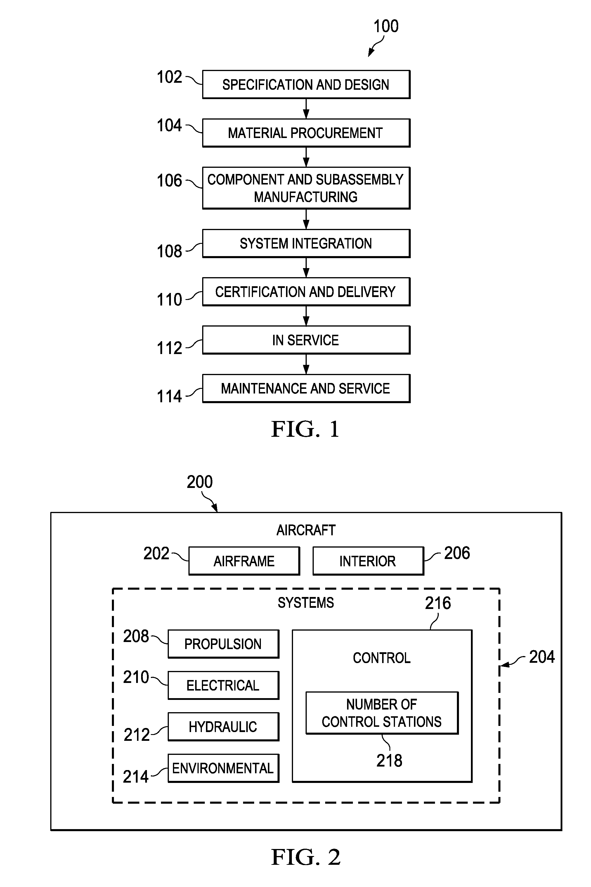
[0035]Referring more particularly to the drawings, embodiments of the disclosure may be described in the context of aircraft manufacturing and service method 100 as shown in FIG. 1 and aircraft 200 as shown in FIG. 2. Turning first to FIG. 1, a diagram illustrating an aircraft manufacturing and service method is depicted in accordance with an illustrative embodiment. During pre-production, aircraft manufacturing and service method 100 may include specification and design 102 of aircraft 200 in FIG. 2 and material procurement 104.

[0036]During production, component and subassembly manufacturing 106 and system integration 108 of aircraft 200 in FIG. 2 takes place. Thereafter, aircraft 200 in FIG. 2 may go through certification and delivery 110 in order to be placed in service 112. While in service by a customer, aircraft 200 in FIG. 2 may be scheduled for routine maintenance and service 114, which may include modification, reconfiguration, refurbishment, and other maintenance or servic...


PUM


Abstract

A method and apparatus for performing a mission. Information for a mission is received at a control station. The control station comprises a display system, a motion capture system, a number of user input devices, a seat associated with the number of user input devices, and a processor unit. The display system is configured to be worn on the head of an operator and to present a display to the operator. The motion capture system is configured to track movement of the head. The processor unit is configured to execute program code to generate the display and adjust the display presented to the operator in response to detecting movement of the head of the operator. The mission is performed using the information and the control station.

Description

BACKGROUND INFORMATION[0001]1. Field[0002]The present disclosure relates generally to a control station and, in particular, to a method and apparatus for a control station for use with a platform. Still more particularly, the present disclosure relates to a control station for use with a platform to perform a mission.[0003]2. Background[0004]Control stations are used for various platforms to control systems and functions for the various platforms. For example, control stations in aerial platforms are used to control sensors, weapons, communications systems, safety functions, navigational systems, flight management, and / or any number of other aerial systems and functions. Control stations are also used in other mobile platforms such as, for example, without limitation, ships, submarines, tanks, spacecraft, space stations, and / or other mobile platforms. Further, control stations are also used for non-mobile platforms such as, for example, ground stations and / or other non-mobile platfo...

Claims


Application Information

Patent Timeline
IPC IPC(8): G06F3/033G09G5/00G06F3/02G06F3/048
CPCG06F3/011A47C7/70G06F3/04815G06F1/163A47C7/624
Inventor EDWARDS, RICHARD E.KESTERSON, BRYAN P.BOUTROS, RAMZYHORNSBY, MARY E.
Owner THE BOEING CO
Learn More