
Transformer

a transformer and transformer technology, applied in the field of transformers, can solve the problems of increasing reducing the expansion or contraction of the adhesive, and being susceptible to mechanical shock

Inactive Publication Date: 2010-12-30
SAMSUNG ELECTRO MECHANICS CO LTD
View PDF9 Cites 2 Cited by
  • Summary
  • Abstract
  • Description
  • Claims
  • Application Information

AI Technical Summary

Problems solved by technology

Since the cores composed of ferrite materials are brittle, they are susceptible to mechanical shock.
Particularly, cracks may easily occur due to thermal shock caused by rapid temperature variations during repeated heating and cooling.
However, due to a large difference in thermal expansion coefficients between the cores and the adhesive, the expansion or contraction of the adhesive is greater than that of the cores during heating or cooling.
Accordingly, considerable thermal stress occurs in the cores, and thus cracks occur at the edges of the connection parts between the center leg parts and the cores.

Method used


Image

  • Transformer
  • Transformer
  • Transformer

Examples


Embodiment Construction

[0024]Exemplary embodiments of the present invention will now be described in detail with reference to the accompanying drawings.

[0025]Also, throughout the drawings, the same reference numerals will be used to designate the same or like parts.

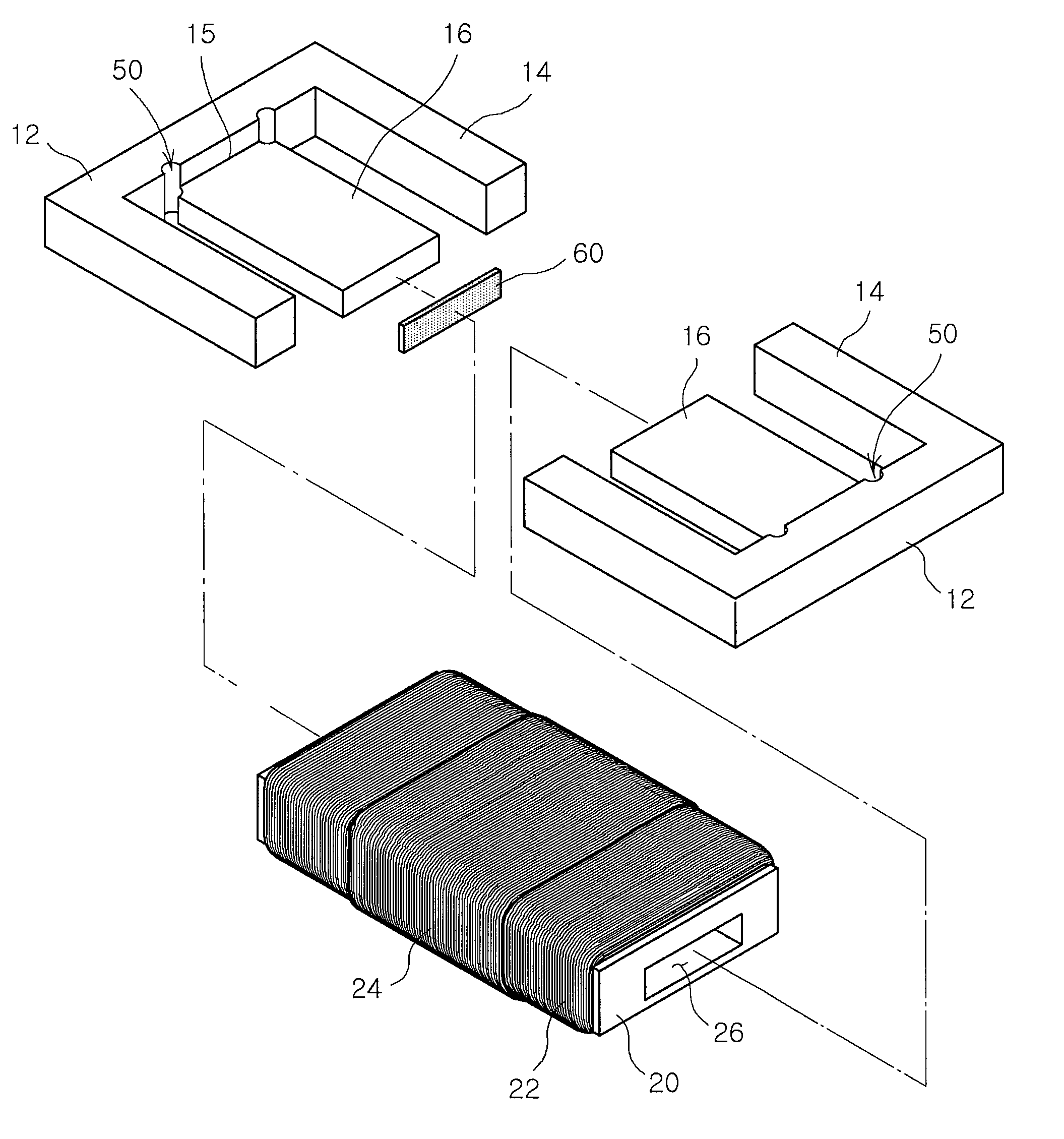
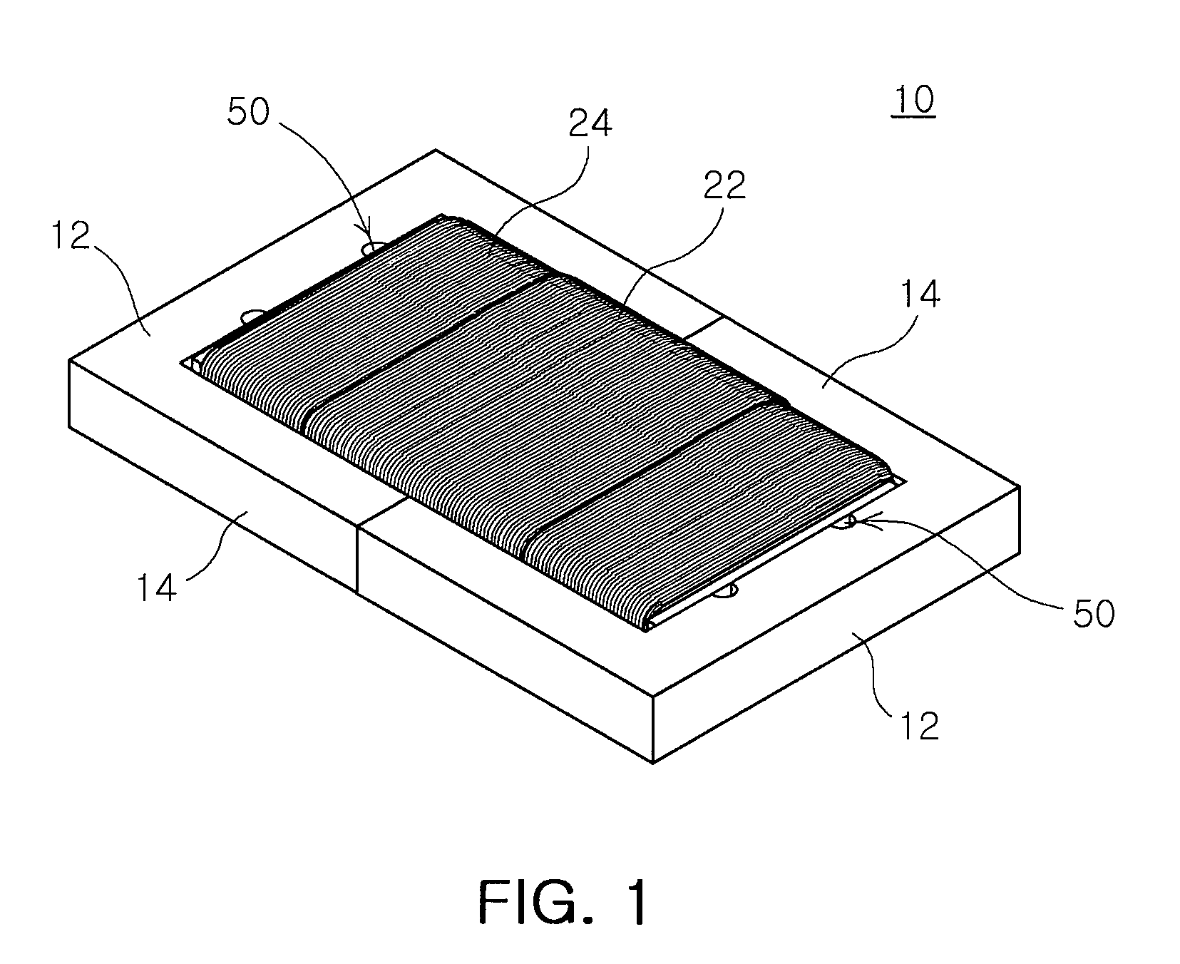
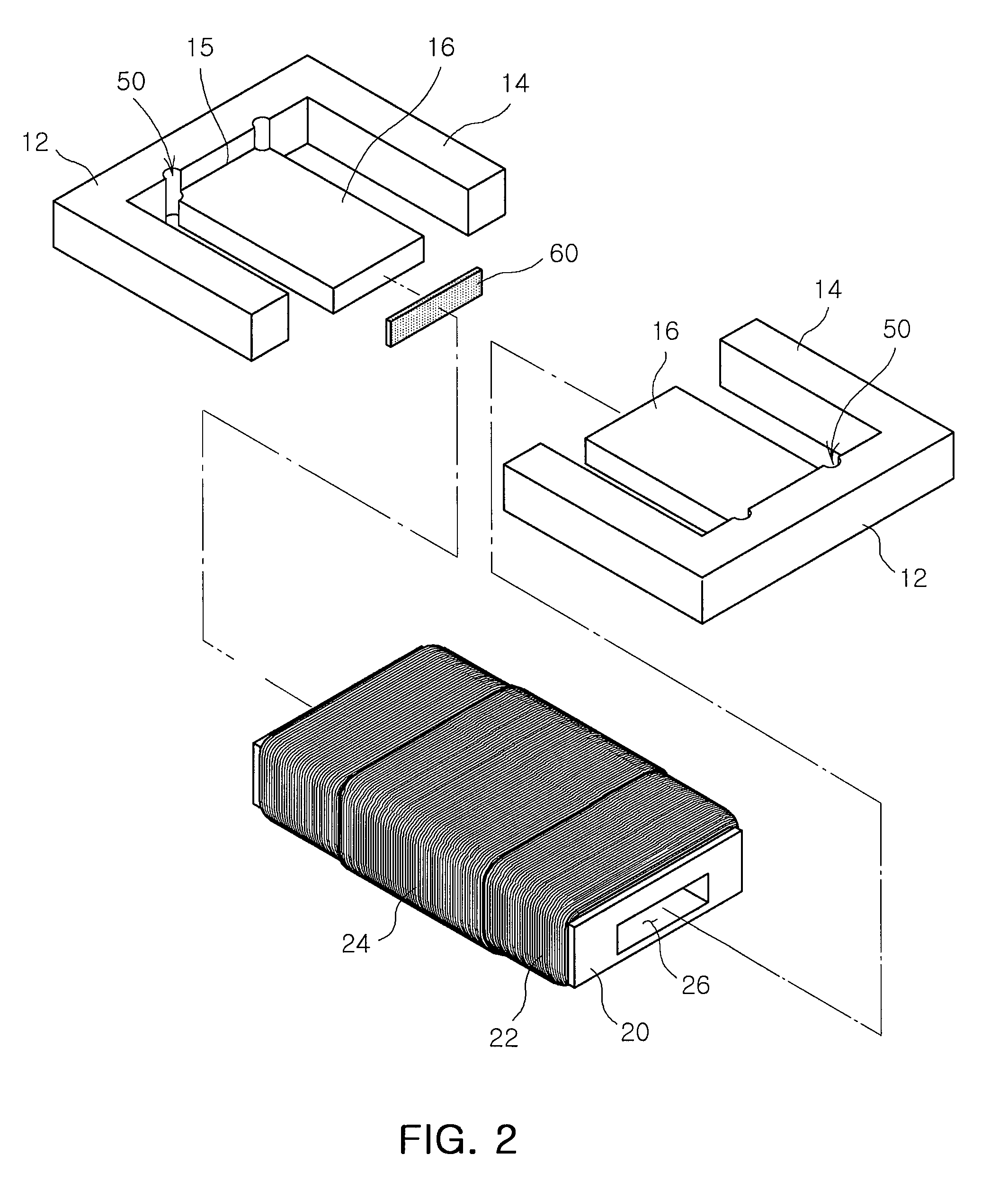
[0026]FIG. 1 is a schematic perspective view of a transformer according to an exemplary embodiment of the present invention. FIG. 2 is an exploded perspective view of a transformer according to an exemplary embodiment of the present invention. FIG. 3 is a cross-sectional view of a transformer according to an exemplary embodiment of the present invention.

[0027]A transformer 10 according to an exemplary embodiment of the invention includes cores 12 and center leg parts 16.

[0028]The cores 12 may be combined with a bobbin 20 wound with coils 22 and 24. The bobbin 20 may have a rectangular cross section. Inside the bobbin 20, a center leg insertion hole 26, in which the center leg parts 16 can be inserted, may be formed. A first coil 22 may be wound...


PUM

PropertyMeasurementUnit
stress concentrationaaaaaaaaaa
temperaturesaaaaaaaaaa

Abstract

There is provided a transformer including cores combined with a bobbin wound with coils, and center leg parts extended from the cores and contacting each other by being inserted into both ends of the bobbin, wherein stress dispersion hole, dispersing stress occurring according to temperature variations around the cores, is formed at the edge of center leg connection parts of the cores from which the center leg parts are extended.

Description

CROSS-REFERENCE TO RELATED APPLICATIONS[0001]This application claims the priority of Korean Patent Application No. 10-2009-0059188 filed on Jun. 30, 2009, in the Korean Intellectual Property Office, the disclosure of which is incorporated herein by reference.BACKGROUND OF THE INVENTION[0002]1. Field of the Invention[0003]The present invention relates to a transformer, and more particularly, to a transformer for preventing cracks from occurring in a center leg connection part extended from a core.[0004]2. Description of the Related Art[0005]A transformer is a device that varies an alternating voltage and a current value using electromagnetic induction, and it is an indispensable element of electronic devices. The transformer is manufactured by winding coils surrounding a large magnetic core. A first coil is connected to an input circuit serving to vary a voltage and a second coil is connected to an output circuit serving to use the varied voltage.[0006]In general, a transformer inclu...

Claims


Application Information

Patent Timeline
Patent Type & Authority Applications(United States)
IPC IPC(8): H01F17/04
CPCH01F27/306H01F27/255H01F27/008
Inventor KIM, HEE SOOOH, YONG JUMOON, SOO DEOKKIM, DONG JIN
Owner SAMSUNG ELECTRO MECHANICS CO LTD
Learn More